Transcription of chapter 1 INTRODUCTION TO DRIVETRAINS
1 1chapter 1 INTRODUCTION TO DRIVETRAINSAll-wheel drive (AWD) 16 Automatic transmission 9 Bevel gear 6 Clutch 8 Constant-velocity (CV) joint 14 Differential 14 Dynamometer 4 Drive axle 14 Driveshaft 14 Final drive 13 Four-wheel drive (4WD) 16 Front-wheel drive (FWD) 13 Gear ratio 7 Half shaft 13 Helical gear 5 Horsepower 3 Hypoid gear 6 Manual transmission 8 Overdrive 7 Pinion gear 8 Pitch diameter 4 Planet carrier 11 Planetary gear set 11 Power transfer unit 16 Rear-wheel drive (RWD) 13 Ring gear 11 Spiral bevel gear 6 Spur gear 5 Sun gear 11 Torque 2 Torque converter 11 Transaxle 13 Transfer case 16 Transmission 8 Universal joint (U-joint) 14 Worm gear 6 KEY TERMSA fter studying this chapter , the reader should be able to:1. Define torque, and explain the relationship between torque and Describe the various gear types and their effect on speed, torque and direction of Explain gear ratios and their effect on vehicle Discuss the types of manual transmissions and transaxles that are currently in Discuss automatic transmissions and the plane-tary gear sets used for automatic Compare rear-wheel drive, front-wheel drive, four-wheel drive, and all-wheel drive Explain the characteristics of drive shafts and drive axle 109/11/16 12:02 pm2 chapter 1 UNITS OF TORQUE Engine torque is developed when combustion pressure pushes a piston downward to rotate the crankshaft.
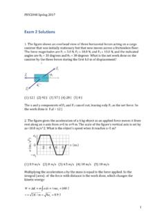
2 SEE FIGURE 1 amount of torque produced will vary depending on the size and design of the engine and the throttle opening. Torque is measured in pounds-feet (lb-ft) or Newton-meters (N-m). One Newton-meter of torque is equal to lb-ft. A factor that greatly affects drivetrain design is that very little or no torque is developed at engine speeds below 1000 RPM ( revolutions per minute ). An engine begins producing usable torque at about 1200 RPM and peak torque at about 2500 to 4000 RPM, with an upper usable speed limit of 5000 to 7000 RPM. The gear ratios in the transmission and drive axle are used to match the engine speed and torque output to the ve-hicle speed and torque requirements.
3 SEE FIGURE 1 VS. DRIVEN GEARS The drive gear is the gear that is the source of the engine torque and rotation. The driven gear is the gear that is driven or rotated by the drive gear. Two gears meshed together are used to transmit torque and rotational motion. The driven gear can then rotate yet another gear. In this case, the second gear becomes the drive gear and the third gear is the driven MULTIPLICATION The gear teeth are cut pro-portional to the diameter of the gear. If one of two mating gears was twice as large as the other, it would have twice as many teeth. For example, if the smaller gear has 10 teeth, a gear twice as large will have 20 teeth. If the teeth of these gears are inter-meshed, 10 teeth of each gear will come into contact when the smaller gear rotates one revolution .
4 This will require one revolu-tion of the small gear and one-half revolution of the larger gear. It will take two revolutions of the small gear to produce one revolution of the larger gear. This is a gear ratio of 2:1, assuming that the small gear is the drive gear. To determine a gear ratio, divide the driven gear by the driving gear. SEE FIGURE 1 AND FUNCTION The purpose of a vehicle drivetrain is to transfer power from the engine to the drive wheels. The drivetrain , also called a powertrain, serves the following functions: It allows the driver to control the power flow. It multiplies the engine torque. It controls the engine Torque is a rotating or twisting force that may or may not result in motion.
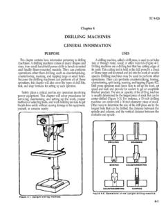
5 A vehicle moves because of the torque the drive axle exerts on the wheels and tires to make them rotate. Being a form of mechanical energy, torque cannot be created or destroyed it is converted from one form of energy to another form of It Lb-Ft or Ft-Lb of Torque?The unit for torque is expressed as a force times the distance (leverage) from the object. Therefore, the official unit for torque is lb-ft (pound-feet) or Newton-meters (a force times a distance). However, it is com-monly expressed in ft-lb and most torque wrenches are labeled with this ASKED QUESTION LENGTH INFEETPULLING FORCEIN POUNDSTWISTING FORCE TORQUE IN FOOT-POUNDSCOMBUSTION PRESSURETORQUEFIGURE 1 1 Torque, a twisting force, is produced when you pull on a wrench.
6 An engine produces torque at the crankshaft as combustion pressure pushes the piston 209/11/16 12:02 pmINTRODUCTION TO DRIVETRAINS 3 GEARS ARE LEVERS Torque is increased because of the length of the gear lever, as measured from the center of the gear. Think of each tooth as a lever, with the fulcrum being the center of the gear. The lever lengths of the two gears can provide leverage much like that of a simple lever. Physics does not allow energy to become lost in a gear set, other than what is lost as heat in overcoming friction. Therefore, whatever power that comes in one shaft, goes out through another. If the speed is reduced, torque will increase by the same amount. If speed is increased, torque will decrease by the same example, if the driving gear has 20 lb-ft (27 N-m) of torque at 500 RPM and the ratio is 2:1, the driven gear will have 40 lb-ft (54 N-m) of torque (twice as much) at 250 RPM (half the speed).
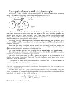
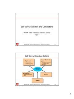
7 RPMTORQUE (FOOT-POUNDS)FIGURE 1 2 The torque produced by a L engine as plotted on a graph. Note that the engine begins producing usable torque at 1000 to 1200 RPM and a maximum torque (381 ft-lb) at 3500 RPM. The torque produced by the engine decreases at higher RPM due to a decrease in volumetric TEETH ON DRIVEN GEAR12 TEETH ON DRIVING GEARFIGURE 1 3 Gear ratio is determined by dividing the number of teeth of the driven (output) gear (24 teeth) by the number of teeth on the driving (input) gear (12 teeth). The ratio illustrated is 2 The term power means the rate of doing work. Power equals work divided by time. Work is done when a certain amount of mass (weight) is moved a certain distance by a force. Whether the object is moved in 10 seconds or 10 minutes does not make a dif-ference in the amount of work accomplished, but it does affect the amount of power needed.
8 SEE FIGURE 1 4. Power is expressed in units of foot-pounds per minute. One horsepower is the power required to move 550 pounds one foot in one second, or 33,000 pounds one foot in one minute (550 lb 60 sec = 33,000 lb). This 309/11/16 12:02 pm4 chapter 1is expressed as 550 foot-pounds (ft-lb) per second or 33,000 foot-pounds per minute. SEE FIGURE 1 AND TORQUE RELATIONSHIP To determine horsepower, a dynamometer is used to measure the amount of torque an engine can produce at various points through its operating range. The formula used to convert torque at a certain revolution per minute (RPM) into a horsepower reading isHorsepower = Torque RPM/5,252 NOTE: To determine how the constant 5,252 was de-rived, perform an Internet search to see an various readings are then plotted into a curve.
9 A typi-cal horsepower and torque curve shows us that an engine does not produce very much torque at low RPM. The most usable torque is produced in the mid-RPM range. Torque decreases with an increase in horsepower at a higher torque from an engine can be increased or decreased through the use of gears, belts, and chains. Gears, belts, or chains cannot increase horsepower; they can only modify its effect. A gear set can increase torque, but it will decrease speed by the same FEET100 LBSFIGURE 1 4 Work is calculated by multiplying force times distance. If you push 100 pounds 10 feet, you have done 1,000 foot-pounds of FEET(50 M)PERMINUTE200 POUNDS(91 KG)165 FEET(50 M)FIGURE 1 5 One horsepower is equal to 33,000 foot-pounds (200 lbs 165 ft) of work per to Explain the Difference between Horsepower and TorqueAs Carroll Shelby, the well-known racer and business owner, said, Horsepower sells cars, but torque wins races.
10 Torque determines how fast the vehicle will accelerate, and horsepower determines how fast the vehicle will TIP PITCH DIAMETERPITCH DIAMETER OFDRIVING GEARPITCH DIAMETER OFDRIVING GEARPOINT APOINT BPOINT CFIGURE 1 6 The pitch diameter is the effective diameter of the gear. Note how the contact points slide on the gear teeth as they move in and out of The effective diameter of a gear is the pitch diameter (or pitch line). SEE FIGURE 1 pitch diameter is the diameter of the gear at the point where the teeth of the two gears meet and transfer power. The gear teeth are shaped to be able to slide in and out of mesh with a minimum amount of friction and wear. Major points include: Driven and driving gears will rotate in opposite 409/11/16 12:02 pmINTRODUCTION TO DRIVETRAINS 5 External gears will always reverse shaft motion.