Transcription of Chapter 12. Brushless DC Motors - Educypedia
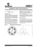
1 Chapter DC MotorsTopics to cover:1. Structures and Drive Circuits2. Equivalent Circuit3. Performance4. ApplicationsIntroductionConventional dc Motors are highly efficient and their characteristics make them suitablefor use as servomotors. However, their only drawback is that they need a commutatorand brushes which are subject to wear and require maintenance. When the functions ofcommutator and brushes were implemented by solid-state switches, maintenance-freemotors were realised. These Motors are now known as Brushless dc this Chapter , the basic structures, drive circuits, fundamental principles, steady statecharacteristics, and applications of Brushless dc Motors will be and Drive CircuitsBasic structuresThe construction of modern Brushless Motors is very similar to the ac motor , known asthe permanent magnet synchronous motor . illustrates the structure of a typicalthree-phase Brushless dc motor .
2 The stator windings are similar to those in a polyphaseac motor , and the rotor is composed of one or more permanent magnets. Brushless dcmotors are different from ac synchronous Motors in that the former incorporates somemeans to detect the rotor position (or magnetic poles) to produce signals to control theelectronic switches as shown in The most common position/pole sensor is theHall element, but some Motors use optical Disassembled view of a Brushless dc motor (from Ref.[1] p58 )48531 EMS Chapter 12. Brushless DC MotorsPage 12-2 LogicCircuitDCSupplyPM acMotorPositionSensorElectronic Brushless dc motor = Permanent magnet ac motor + Electronic commutatorAlthough the most orthodox and efficient Motors are three-phase, two-phase brushlessdc Motors are also very commonly used for the simple construction and drive shows the cross section of a two-phase motor having auxiliary salient of conventional and Brushless dc motorsAlthough it is said that Brushless dc Motors and conventionaldc Motors are similar in their static characteristics, theyactually have remarkable differences in some aspects.
3 Whenwe compare both Motors in terms of present-day technology,a discussion of their differences rather than their similaritiescan be more helpful in understanding their properapplications. Table 1 compares the advantages anddisadvantages of these two types of Motors . When wediscuss the functions of electrical Motors , we should notforget the significance of windings and refers to the process which converts the input direct current to alternatingcurrent and properly distributes it to each winding in the armature. In a conventional dcmotor, commutation is undertaken by brushes and commutator; in contrast, in abrushless dc motor it is done by using semiconductor devices such as Two-phase motorhaving auxiliary salient poles(from Ref.[1] p95 )48531 EMS Chapter 12. Brushless DC MotorsPage 12-3 Drive circuits(1) Unipolar illustrates a simple three-phase unipolar-operated motor that uses optical sensors(phototransistors) as position detectors.
4 Three phototransistors PT1, PT2, and PT3 areplaced on the end-plate at 120o intervals, and are exposed to light in sequence through arevolving shutter coupled to the motor shown in , the north pole of the rotor now faces the salient pole P2 of the stator,and the phototransistor PT1 detects the light and turns transistor Tr1 on. In this state, thesouth pole which is created at the salient pole P1 by the electrical current flowingthrough the winding W1 is attracting the north pole of the rotor to move it in thedirection of the arrow. When the north pole comes to the position to face the salient poleP1, the shutter, which is coupled to the shaft, will shade PT1, and PT2 will be exposedto the light and a current will flow through the transistor Tr2. When a current flowsthrough the winding W2, and creates a south pole on salient pole P2, then the north polein the rotor will revolve in the direction of the arrow and face the salient pole P2.
5 At thismoment, the shutter shades PT2, and the phototransistor PT3 is exposed to the actions steer the current from the winding W2 to W3. Thus salient pole P2 is de-energized, while the salient pole P3 is energized and creates the south pole. Hence thenorth pole on the rotor further travels from P2 to P3 without stopping. By repeating sucha switching action in sequence given in , the permanent magnet rotor revolvescontinuously. unipolar-driven Brushless dc motor (from Ref.[1] p59 with winding directions swapped)48531 EMS Chapter 12. Brushless DC MotorsPage 12-4 sequence and rotation of stator's magnetic field (from Ref.[1] p60 )(2) Bipolar driveWhen a three-phase ( Brushless ) motor is driven by a three-phase bridge circuit, theefficiency, which is the ratio of the mechanical output power to the electrical inputpower, is the highest, since in this drive an alternating current flows through eachwinding as an ac motor .
6 This drive is often referred to as 'bipolar drive'. Here, 'bipolar'means that a winding is alternatively energised in the south and north shall now survey the principle of the three-phase bridge circuit of Here too,we use the optical method for detecting the rotor position; six phototransistors areplaced on the end-plate at equal intervals. Since a shutter is coupled to the shaft, thesephoto elements are exposed in sequence to the light emitted from a lamp placed in theleft of the figure. Now the problem is the relation between the ON/OFF state of thetransistors and the light detecting phototransistors. The simplest relation is set when thelogic sequencer is arranged in such a way that when a phototransistor marked with acertain number is exposed to light, the transistor of the same number turns ON. that electrical currents flow through Tr1, Tr4, and Tr5, and terminals U and Whave the battery voltage, while terminal V has zero potential.
7 In this state, a current willflow from terminal U to V, and another current from W to V as illustrated in Wemay assume that the solid arrows in this figure indicate the directions of the magneticfields generated by the currents in each phase. The fat arrow in the centre is the resultantmagnetic field in the EMS Chapter 12. Brushless DC MotorsPage phase bipolar-driven Brushless motor (from Ref.[1] p61, )The rotor is placed in such a position that the field flux will have a 90o angle withrespect to the stator's magnetic field as shown in In such a state a clockwisetorque will be produced on the rotor. After it revolves through about 30o, PT5 is turnedOFF and PT6 ON which makes the stator's magnetic pole revolve 60o clockwise. Thuswhen the rotor's south pole gets near, the stator's south pole goes away further to create acontinuous clockwise rotation. The ON-OFF sequence and the rotation of the transistorare shown in 's magnetic field in the shutter state of , and the directionof torque (from Ref.)
8 [1] p62, ) revolutions of the stator's magnetic field and rotor (from Ref.[1] p63 )48531 EMS Chapter 12. Brushless DC MotorsPage 12-6 The rotational direction may be reversed by arranging the logic sequencer in such a waythat when a photodetector marked with a certain number is exposed to light, thetransistor of the same number is turned OFF. On the other hand, when a phototransistoris not exposed to light, the transistor of the same number is turned the positional state of , Tr2, 3, and 6 are ON, and the battery voltage E appears atterminal V, while U and W have zero electric potential. Then, as shown in (a), themagnetic field in the stator is reversed, and the rotor's torque is counter-clockwise. Afterthe motor revolves about 30o, Tr2 turns OFF and Tr1 ON. At this point, the field hasrevolved 60o and becomes as shown in (b). As the rotor produces another counter-clockwise torque, the counter-clockwise motion continues and the field becomes asshown in (c).
9 This action is replaced in the sequence of (a) (b) (c) (d).. toproduce a continuous counter-clockwise Counter-clockwise revolutions of the stator's magnetic field and rotor (from Ref.[1] p63 )The motor discussed above has -connected windings, but it may also have Y-connected windings. (a) shows a practical circuit which is used in a laser-beamprinter or a hard-disc drive. As shown in (b), three Hall elements are placed atintervals of 60o for detection of the rotor's magnetic poles. Because this motor has fourmagnetic poles, a mechanical angle of 60o corresponds to an electrical angle of Circuit and General EquationsThe per phase equivalent circuit is shown in as following, where m is the fluxlinkage of stator winding per phase due to the permanent steady state conditions, assuming v and e are sinusoidal at frequency , theequivalent circuit becomes the one shown in , where X= L, and V, I, E, and mare phasors with rms amplitudes.
10 The steady state circuit equation can be written as V = E + ( R + j L ) I(1)48531 EMS Chapter 12. Brushless DC MotorsPage 12-7 circuit for a three-phase bipolar-driven motor , and arrangement of Hall elements (from Ref.[1] p80 )e =d per phase equivalent circuit of Brushless dc motorsVIRX = LE = j state per phase equivalent circuit of Brushless dc motorsFor a maximum mechanical power at a given speed, I and E are in phase. This also givesmaximum torque/ampere (minimum current/Nm). A Brushless dc motor has positionfeedback from the rotor via Hall devices, optical devices, encoder etc. to keep aparticular angle between V and E, since E is in phase with rotor position, and V is48531 EMS Chapter 12. Brushless DC MotorsPage 12-8determined by the inverter supply to the motor . Assuming that L<<R, when I is inphase with E, V will also be in phase with E. Thus the circuit can be analyzed usingmagnitudes of E, V, and I as if it were a dc first note that when E and I are in phase, the motor mechanical power output (beforefriction, windage, and iron losses) the electromagnetic output power is Pem = m |E| |I| = m | m| |I|(2)where m is the number of phases, |E|, |I|, and | m| are the amplitudes of phasor E, I, and m, and the electromagnetic torque is Tem = Pem r = mIm ||||r(3)where r = 2 /p is the rotor speed in Rad/s, and p the number of poles.