Transcription of Chapter 19 Programming the PID Algorithm - utoledo.edu
1 Ch 19 PID block 1 Chapter 19 Programming the PID Algorithm Introduction The PID Algorithm is used to control an analog process having a single control point and a single feedback signal. The PID Algorithm controls the output to the control point so that a setpoint is achieved. The setpoint may be entered as a static variable or as a dynamic variable that is calculated from a mathematical operation. For many years, the PID Algorithm was not accepted as a function suitable for a PLC. It was included in a DCS (Distributed Control System) or configured from a number of stand-alone PID controllers. However, as PLC prices continued to fall during the 1980 s and later and more economical HMI systems were developed for the PLC, PLCs became more accepted as PID controllers. In fact, because PLCs have undercut the cost of competing systems, DCSs and other PID controllers have been forced to drop prices dramatically or no longer remain competitive. An early hybrid design was introduced into the Allen-Bradley 1771 I/O family including 2 PID stand-alone controllers attached to a single I/O slot and executing the PID Algorithm from the controller in the I/O slot.
2 Newer control schemes have the PID Algorithm executing in the PLC with other programs and controlling complicated processes with good success. Chapter 19 uses the PID block to control a simple process. Then, it discusses more complex operations capable of being programmed by the PID control block . The Chapter describes the SLC PID block followed by the CompactLogix processor as well as the Siemens 1200 and their implementations of the PID function. Using these various PLC configurations demonstrates differences between the newer PID blocks and the SLC PID block . The SLC processor uses an integer-based PID block . Integer-based blocks have the disadvantage that scaling must be used to convert numbers to more meaningful real values. Scaling adds complexity to the program that becomes transparent with a floating-point PID block . More sophisticated PID blocks such as is available in the PLC/5 and ControLogix processors as well as Siemens allow floating-point calculations.
3 These more robust PID blocks also provide more sophistication in their functionality. All PID blocks are not created equal. Fundamentals of Closed Loop Control Closed Loop Control Tasks "Closed loop control is a process where the value of a variable is established and maintained continuously through intervention based on measurements of this variable. This generates a sequence of effects that takes place in a closed loop -the control loop- because the process runs based on measurements of a variable that is influenced in turn by itself. This variable that is to be controlled is measured continuously and compared with another specified variable of the same type. Depending on the result of this comparison, an adaptation of the variable to be controlled to the value of the specified variable is performed by the control process. Proportional Controller (P-Controller) In the case of P-controllers, the manipulated variable is always proportional to the recorded system deviation.
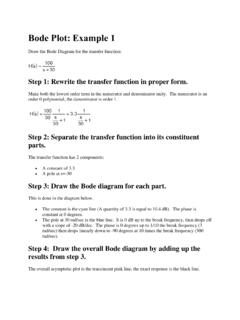
4 The result is that a P-controller reacts without a delay to a deviation and generates a manipulated variable only if the deviation (error) is present. The proportional pressure regulator sketched in the figure below compares the power FS of the setpoint spring with Ch 19 PID block 2 the power FB that the pressure P2 generates in the spring-elastic metal bellows. If the forces are off balance, the lever rotates around the pivot point D. The valve position changes and accordingly the pressure P2 to be regulated until a new balance of forces is established. The behavior of the P-controller if a system deviation suddenly occurs is shown in the figure below. The amplitude of the manipulated variable jump y depends on the level of the deviation e and the amount of the proportional coefficient Kp: To keep the deviation low, a proportionality factor as large as possible has to be selected. Increasing the factor causes the controller to respond faster.
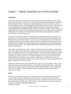
5 However, a value that is too high may cause overshooting and a large hunting tendency on the part of the controller. 2 1 ( )= ( ) ( ) ( )= The diagram below shows the behavior of the P-controller: SetpointActualvalueDeviationControlvaria bletime Metal bellows Setpoint spring Fig. 19-1 Fig. 19-2 Ch 19 PID block 3 The advantages of this type of controller consist on the one hand of its simplicity (electronic implementation can, in the simplest case, consist of merely a resistor), and on the other hand its prompt response in comparison to other controller types. The main disadvantage of the P-controller is the continuous deviation; the setpoint is never completely attained, even long term. This disadvantage as well as the not yet ideal response speed can be minimized only insufficiently with a larger proportionality factor, since otherwise the controller will overshoot. In the most unfavorable case, the controller will enter a state of continuous oscillation.
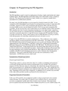
6 This causes the controlled variable to be periodically moved away from the setpoint, not by the influencing variable but by the controller. The problem of continuous deviation is solved best with an integral controller. Integral Controller (I-Controller) Integrating controllers are used to completely correct system deviations at each operating point. As long as the deviation is unequal to zero, the manipulated variable continues to change. Only when the reference variable and the controlled variable are equal is the control system in a steady state. The mathematical formulation of this integral behavior is as follows: = ( ) =1 How fast the manipulated variable rises (or falls) depends on the deviation and the integration time. PI-Controller The PI-controller is a type often used in practice. It results from connecting a P-controller and an I-controller in parallel. When laid out correctly it unites the advantages of both controller types (stable and fast, no permanent system deviation), so that their disadvantages are compensated at the same time.
7 block diagram Fig. 19-3 Ch 19 PID block 4 The behavior with respect to time is identified by the proportional coefficient Kp and the reset time Tn. Because of the proportional component, the manipulated variable responds immediately to every system deviation e, while the integral component takes effect only in the course of time. Tn represents the time that passes until the I-component generates the same amplitude of flow as occurs immediately because of the P-component (Kp). As in the case of the I-controller, the reset time Tn has to be decreased if we want to increase the integral component. Differential Controller (D-Controller) The D-controller generates its manipulated variable from the rate of change of the system deviation, and not, as the P-controller, from its amplitude. For that reason, it responds considerably faster than the P-controller. Even if the deviation is small, it generates (looking ahead) large amplitudes of flow as soon as an amplitude change occurs.
8 However, the D-controller does not detect permanent deviations, because no matter how large it is, its rate of change equals zero. For that reason, the D-controller is used only rarely by itself in practice. Rather, it is used jointly with other control elements, usually in connection with a proportional component. PID Controller If we expand the PI controller with a D-component, the universal PID controller is created. As in the case of the PD controller, adding the D-component has the effect that, if laid out correctly, the controlled variable reaches its setpoint sooner and its steady state faster. block diagram Fig. 19-4 Ch 19 PID block 5 = + + with = , = Fig. 19-5 PID Diagrams and Equations Objectives of Control System Setting For the control result to be satisfactory, selecting a suitable controller is an important aspect. However, even more important is setting the suitable controller parameters Kp, Tn and Tv, that have to be adjusted to the controlled system behavior.
9 Usually, we have to compromise between a very stable but slow control system or a very dynamic, more unsettled control performance which under certain circumstances has a tendency to oscillate and can become unstable. In the case of non-linear systems that are always to process at the same operating point -such as fixed setpoint control- the controller parameters have to be adjusted to the controlled system behavior at this working point. If, as in the case of servo controls, a fixed working point cannot be defined, a controller setting has to be found that supplies a sufficiently fast and stable control result over the entire working range. In practice, controllers are usually set based on values arrived at through experience. If these are not available, the controlled system behavior has to be analyzed exactly, in order to subsequently -with the aid of theoretical or practical layout procedures - specify suitable controller parameters. Ch 19 PID block 6 An Example SLC PID Function In its simplest form, the SLC PID block is used as a single block with no input contacts and surrounded by only two SCP blocks.
10 This PID instruction is located in Ladder 2. The SCP block is configured to retrieve a numerical value from the analog input channel, linearly scale the input and move the resultant value to the PID block . The input is a 4-20 mA signal from a flow transmitter. The output is a 4-20 mA signal to a variable flow valve. SCP Scale with Parameters Input Input Min Input Max Scaled Min Scaled Max Ouptut PID Control block Process Variable Control Variable Control block Length SCP Scale with Parameters Input Input Min Input Max Scaled Min Scaled Max Output Fig. 19-6 Simple Program of PID for SLC Processor Ch 19 PID block 7 In the first SCP instruction, values found in the Input Min and Input Max of the SCP instruction are from the I/O card. The engineer must first decide which I/O card to use and then find the proper lower and upper limits from the literature on the card to enter values in the SCP instruction. In this case, the analog card selected is the 1746-NIO4I Ser.
![CHAP. 7] BLOCK DIAGRAM ALGEBRA AND TRANSFER …](/cache/preview/5/5/8/8/1/3/4/c/thumb-5588134cce7b9b85f7cd5a0611a184e9.jpg)