Transcription of Chapter 2 Central Processing Unit - IOE Notes
1 computer organization and Architecture Chapter 2 : Central Processing Unit Compiled By: Er. Hari Aryal References: W. Stalling & M. Mano | 1 Chapter 2 Central Processing Unit The part of the computer that performs the bulk of data Processing operations is called the Central Processing Unit (CPU) and is the Central component of a digital computer . Its purpose is to interpret instruction cycles received from memory and perform arithmetic, logic and control operations with data stored in internal register, memory words and I/O interface units. A CPU is usually divided into two parts namely processor unit (Register Unit and Arithmetic Logic Unit) and control unit.
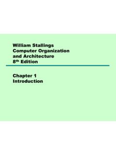
2 Fig: Components of CPU Processor Unit: The processor unit consists of arithmetic unit, logic unit, a number of registers and internal buses that provides data path for transfer of information between register and arithmetic logic unit. The block diagram of processor unit is shown in figure below where all registers are connected through common buses. The registers communicate each other not only for direct data transfer but also while performing various micro-operations. Here two sets of multiplexers select register which perform input data for ALU. A decoder selects destination register by enabling its load input. The function select in ALU determines the particular operation that to be performed.
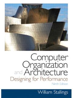
3 For an example to perform the operation: R3 R1 + R2 1. MUX A selector (SELA): to place the content of R1 into bus A. 2. MUX B selector (SELB): to place the content of R2 into bus B. 3. ALU operation selector (OPR): to provide arithmetic addition A + B. 4. Decoder destination selector (SELD): to transfer the content of the output bus into R3. computer organization and Architecture Chapter 2 : Central Processing Unit Compiled By: Er. Hari Aryal References: W. Stalling & M. Mano | 2 Fig: Processor Unit Control unit: The control unit is the heart of CPU. It consists of a program counter, instruction register, timing and control logic.
4 The control logic may be either hardwired or micro-programmed. If it is a hardwired, register decodes and a set of gates are connected to provide the logic that determines the action required to execute various instructions. A micro-programmed control unit uses a control memory to store micro instructions and a sequence to determine the order by which the instructions are read from control memory. The control unit decides what the instructions mean and directs the necessary data to be moved from memory to ALU. Control unit must communicate with both ALU and main memory and coordinates all activities of processor unit, peripheral devices and storage devices.
5 It can be characterized on the basis of design and implementation by: Defining basic elements of the processor Describing the micro-operation that processor performs Determining the function that the control unit must perform to cause the micro-operations to be performed. Control unit must have inputs that allow determining the state of system and outputs that allow controlling the behavior of system. The input to control unit are: Flag: flags are headed to determine the status of processor and outcome of previous ALU operation. computer organization and Architecture Chapter 2 : Central Processing Unit Compiled By: Er. Hari Aryal References: W.
6 Stalling & M. Mano | 3 Clock: All micro-operations are performed within each clock pulse. This clock pulse is also called as processor cycle time or clock cycle time. Instruction Register: The op-code of instruction determines which micro-operation to perform during execution cycle. Control signal from control bus: The control bus portion of system bus provides interrupt, acknowledgement signals to control unit. The outputs from control unit are: Control signal within processor: These signals causes data transfer between registers, activate ALU functions. Control signal to control bus: These are signals to memory and I/O module. All these control signals are applied directly as binary inputs to individual logic gate.
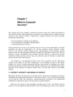
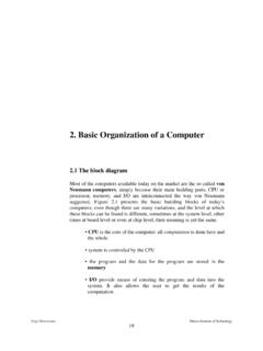
7 Fig: Control Unit CPU Structure and Function Processor organization Things a CPU must do: - Fetch Instructions - Interpret Instructions - Fetch Data - Process Data - Write Data computer organization and Architecture Chapter 2 : Central Processing Unit Compiled By: Er. Hari Aryal References: W. Stalling & M. Mano | 4 Fig: The CPU with the System Bus A small amount of internal memory, called the registers, is needed by the CPU to fulfill these requirements Fig: Internal Structure of the CPU Components of the CPU - Arithmetic and Logic Unit (ALU): does the actual computation or Processing of data - Control Unit (CU): controls the movement of data and instructions into and out of the CPU and controls the operation of the ALU.
8 Register organization Registers are at top of the memory hierarchy. They serve two functions: 1. User-Visible Registers - enable the machine- or assembly-language programmer to minimize main-memory references by optimizing use of registers 2. Control and Status Registers - used by the control unit to control the operation computer organization and Architecture Chapter 2 : Central Processing Unit Compiled By: Er. Hari Aryal References: W. Stalling & M. Mano | 5 of the CPU and by privileged, OS programs to control the execution of programs User-Visible Registers Categories of Use - General Purpose registers - for variety of functions - Data registers - hold data - Address registers - hold address information - Segment pointers - hold base address of the segment in use - Index registers - used for indexed addressing and may be auto indexed - Stack Pointer - a dedicated register that points to top of a stack.
9 Push, pop, and other stack instructions need not contain an explicit stack operand. - Condition Codes (flags) Design Issues Completely general-purpose registers or specialized use? - Specialized registers save bits in instructions because their use can be implicit - General-purpose registers are more flexible - Trend is toward use of specialized registers Number of registers provided? - More registers require more operand specifier bits in instructions - 8 to 32 registers appears optimum (RISC systems use hundreds, but are a completely different approach) Register Length? - Address registers must be long enough to hold the largest address - Data registers should be able to hold values of most data types - Some machines allow two contiguous registers for double-length values Automatic or manual save of condition codes?
10 - Condition restore is usually automatic upon call return - Saving condition code registers may be automatic upon call instruction, or may be manual Control and Status Registers Essential to instruction execution - Program Counter (PC) - Instruction Register (IR) - Memory Address Register (MAR) - usually connected directly to address lines of bus - Memory Buffer Register (MBR) - usually connected directly to data lines of bus Program Status Word (PSW) - also essential, common fields or flags contained include: - Sign - sign bit of last arithmetic operation - Zero - set when result of last arithmetic operation is 0 - Carry - set if last op resulted in a carry into or borrow out of a high-order bit - Equal - set if a logical compare result is equality - Overflow - set when last arithmetic operation caused overflow - Interrupt Enable/Disable - used to enable or disable interrupts - Supervisor - indicates if privileged ops can be used computer organization and Architecture Chapter 2 : Central Processing Unit Compiled By: Er.