Transcription of CHAPTER 2 DYNAMIC FORCE ANALYSIS
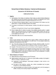
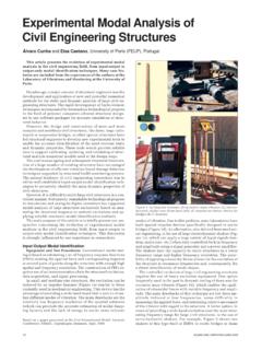
1 CHAPTER 2 DYNAMIC FORCE ANALYSIS When the inertia forces are considered in the ANALYSIS of the mechanism, the ANALYSIS is known as DYNAMIC FORCE ANALYSIS . Now applying D Alembert principle one may reduce a DYNAMIC system into an equivalent static system and use the techniques used in static FORCE ANALYSIS to study the system. Inertia FORCE and couple Figure 1: Illustration of inertia FORCE (i) a translating body (ii) a compound pendulum, (iii) inertia FORCE and couple on compound pendulum. Consider a body of mass moving with acceleration as shown in figure 1(i). According to D Alembert Principle, the body can be brought to equilibrium position by applying a FORCE equal to maiFma=and in a direction opposite to the direction of acceleration. Figure 1 (ii) shows a compound pendulum of mass m, moment of inertia gIabout center of mass G while rotating at its center of mass has a linear acceleration of and angular acceleration of a.
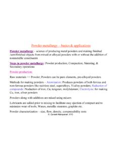
2 Figure 1(iii) shows the inertia FORCE and couple acting on the pendulum. Equivalent off-set Inertia FORCE Figure 2: (i) Illustration of equivalent off-set inertia FORCE Figure 2(i) shows a body with inertia FORCE iF and inertia couplecI. The couple can be replaced by two parallel forces (equal in magnitude and opposite in direction) acting at G and H respectively as shown in Figure 2(ii). If we consider their magnitude of these forces same as that of inertia FORCE , then the equal amiFma=aG ma g G maG H iF H G iF cI(i) iF iF iF H G G (iv) (iii) (ii) 30and opposite forces at point G will cancel each other and the resulting FORCE will be a FORCE at H which is in the same direction as inertia FORCE . If h is the minimum distance between the FORCE at G and H, then ciIhF= where and ciIF are magnitude of cI and iF respectively. This FORCE acting at H is known as equivalent offset inertia FORCE .
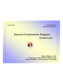
3 For the compound pendulum shown in Figure 1(iii), the equivalent offset inertia FORCE is shown in Figure 2(iii). DYNAMIC FORCE ANALYSIS of four bar mechanism Let us study the four bar mechanism where are mass of link 2,3 and 4 respectively. We have to find the torque required at link 2 for DYNAMIC equilibrium when an external FORCE acts on link 4 as shown in figure 3. Now for DYNAMIC FORCE ANALYSIS the following steps may be followed. 234, and mmm4F External FORCE T F4 Figure 1: Four bar mechanism showing external and constraint forces Draw the acceleration diagram or use any analytical method to determine acceleration Determine angular acceleration of link 2,3 and 4.
4 Determine linear acceleration of center of mass (2, 3, 4giai=) of link 2 3 and 4 . The magnitude of inertia FORCE of link ii(2,3 or 4)=can be determined by multiplying mass of link iwith the corresponding acceleration of the center of mass. The direction of the inertia FORCE is opposite to the direction of the acceleration. Determine the magnitude of inertia couple which is equal to iiI The direction of the inertia couple is opposite to that of angular acceleration. Replace the inertia FORCE and couple by the equivalent offset inertia FORCE for each link. Treat these offset inertia FORCE as external FORCE and follow the procedure for static FORCE ANALYSIS . One may use either super-position principle or principle of virtual work to find the required torque for equilibrium. giigiFma= 31 DYNAMIC FORCE ANALYSIS of a Four bar Mechanism using Matrix Method In the four bar mechanism shown in Figure 1, Link 1 is the ground link (sometimes called the frame or fixed link), and is assumed to be motionless.
5 Links 2 and 4 each rotate relative to the ground link about fixed pivots (A and D). Link 3 is called the coupler link, and is the only link that can trace paths of arbitrary shape (because it is not rotating about a fixed pivot). Usually one of the "grounded links" (link 2 or 4) serves as the input link, which is the link which may either be turned by hand, or perhaps driven by an electric motor or a hydraulic or pneumatic cylinder. If link 2 is the input link, then link 4 is called the follower link, because its rotation merely follows the motion as determined by the input and coupler link motion. If link 2 is the input link and its possible range of motion is unlimited, it is called a crank, and the linkage is called a crank-rocker. Crank-rockers are very useful because the input link can be rotated continuously while a point on its coupler traces a closed complex curve. A Simple four-bar linkage. The DYNAMIC FORCE ANALYSIS problem was solved using the matrix method by reducing it to one requiring static ANALYSIS .
6 For this purpose, D Alembert s Principle which states that the inertia forces and couples, and the external forces and torques on the body together give statically equilibrium, was considered. The inertia forces Fgi s and inertia moments Tgi s are given by, giiFmagi= (1) giiTIgi = (2) 32where, mi is the mass of the link i, Ii is the moment of inertia about an axis passing through the centre of mass gi and perpendicular to plane of rotation of the link i, agi and gi are the acceleration and angular acceleration of the centre of mass of the ith link respectively. The Free-body diagrams of (a) Link 2(crank/input link) (b) Link 3(coupler) (c) Link 4(follower link) Given position, velocity, acceleration, and inertia properties such as mass and mass moment of inertia for each moving link of a four-bar linkage, FORCE ANALYSIS for the linkage can be performed. From the free body diagrams ( ) three static equilibrium equations, in terms of forces in the X and Y directions and moment about the center of gravity of the link, can be written for each link.
7 For link 2, we get 123220xxgxFFF++= (3) 2123220gyygymFFF +++= (4) 21222322()sgggTrFrrFT + +=0) (5) where, (2222exp()ggrri =+ is the position vector from joint A to the center of gravity of link 2. and are the joint forces acting on link 2. 12F32F2gF and 2gTare the inertia FORCE and inertia moment of link 2. is the mass of link 2 and Ts is the driving torque. Similarly for link 3, we get 2m 33234330xxgxFFF++= (6) 3234330gyygymFFF +++= (7) 32333433()gggrFrrFT + +=0) (8) where, (3333exp()ggrri =+ is the position vector from joint B to the center of gravity of link 3. and are the joint forces acting on link 3. 23F43F3gF and 3gT are the inertia FORCE and inertia moment of link 3. is the mass of link 3. Similarly for link 4, we get 3m 341440xxgxFFF++= (9) 4341440gyygymFFF +++= (10) 414443441()gggrFrrFTT + ++=0) (11) where, (4444exp()ggrri =+ is the position vector from joint D to the center of gravity of link 4.
8 And are the joint forces acting on link 4. 14F34F4gF and 4gT are the inertia FORCE and inertia moment of link 4. is the mass of link 4 and is the torque of external load. 4m1T The equations (5), (8), and (11) can be expressed as, ()()222122221222222322222322cos()sin()co scos()sincos()02sgygxggxgTrFrFrrFrrFT ++++ + ++=y (12) ()()333233332333333433333433cos()sin()co scos()sincos()03gygxggxgrFrFrrrrFT ++++ + ++=yF (13) ()()4441444414444443444444344cos()sin()c oscos()sincos()0gygxggxgrFrFrrrrFT ++++ + ++=yF (14) Here, it was taken into account thatijxjixFF= and ijyjiyFF= . Thus the equations (3 -11) can be written as nine linear equations in terms of nine unknowns. They can be expressed in a symbolic form Axb= (15) where, = the transpose of ( ) and is a vector consisting of the unknown forces and input torque, b = the transpose of () and is a vector that contains external load plus inertia forces and inertia torques.
9 And the matrix A which is a 9x9 matrix, is found to be x12,12,23,23,34,34,14,14,xyxyxyxyFFFFFFF FTs,,,,,,,gxgygggxgygggxggFFmTFFmTFmTT +222233334441 341 0 -1 0 0 0 0 0 0 0 1 0 -1 0 0 0 0 0 222sin()gr + 222cos()gr + 22222sincos()grr + 22222coscos()grr ++ 0 0 0 0 1 0 0 1 0 -1 0 0 0 0 0 0 0 1 0 -1 0 0 0 0 0 333sin()gr + 333cos()gr + 33333sincos()grr + 33333coscos()
10 Grr ++ 0 0 0 0 0 0 0 1 0 1 0 0 0 0 0 0 0 1 0 1 0 0 0 0 0 44444sincos()grr ++ 44344coscos()grr ++ 444sin()gr + 444cos()gr + 0 Solution procedure A large number of inputs are required from the user, viz. link lengthhs of the four links, their masses, radius of gyration and departures of the centre of mass from the link positions ( angle ), input angle, initial angular velocity, angular acceleration and the external load torque.