Transcription of CHAPTER 2 HYDRAULICS OF SEWERS - New Jersey Institute …
1 3 CHAPTER 2 HYDRAULICS OF SEWERSThe hydraulic design procedure for SEWERS requires:1. Determination of sewer System Type2. Determination of Design Flow3. Selection of Pipe Size4. Determination of Flow VelocitySANITARY SEWERSDETERMINATION OF sewer SYSTEM TYPES anitary SEWERS are designed to carry domestic, commercial and industrialsewage with consideration given to possible infiltration of ground water. All typesof flow are designed on the basis of having the flow characteristics of OF DESIGN FLOWIn designing sanitary SEWERS , average, peak and minimum flows areconsidered.
2 Average flow is determined or selected, and a factor applied to arriveat the peak flow which is used for selecting pipe size. Minimum flows are used todetermine if specified velocities can be maintained to prevent deposition of Flow. The average flow, usually expressed in gallons per day, is ahypothetical quantity which is derived from past data and experience. Withadequate local historical records, the average rate of water consumption can berelated to the average sewage flow from domestic, commercial and industrialsources. Without such records, information on probable average flows can beobtained from other sources such as state or national agencies.
3 Requirements forminimum average flows are usually specified by local or state sanitary authoritiesor local, state and national public health agencies. Table 1 lists design criteria fordomestic sewage flows for various municipalities. Commercial and industrialsewage flows are listed in Table 2. These tables were adapted from the Designand Construction of Sanitary and Storm SEWERS , published by American Societyof Civil Engineers and Water Pollution Control Federation. To apply flow criteria inthe design of a sewer system, it is necessary to determine present and futurezoning, population densities and types of business and Flow.
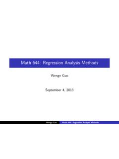
4 The actual flow in a sanitary sewer is variable, and many studieshave been made of hourly, daily and seasonal variations. Typical results of onestudy are shown in Figure I adapted from Design and Construction of Sanitaryand Storm SEWERS , published by the American Society of Civil Engineers andWater Pollution Control Federation. Maximum and minimum daily flows are usedin the design of treatment plants, but the sanitary sewer must carry the peak flow4 Concrete Pipe Design ManualAmerican Concrete Pipe Association 222 W. Las Colinas Blvd.
5 , Suite 641 Irving, Texas 75039-5423 972-506-7216 Fax 972-506-7682that will occur during its design life. This peak flow is defined as the mean rate ofthe maximum flow occurring during a 15-minute period for any 12-month periodand is determined by multiplying average daily flow by an appropriate of this factor range from to for design populations of onethousand, to a factor of to for design population of one million. Tables 1and 2 list minimum peak loads used by some municipalities as a basis for Flow. A minimum velocity of 2 feet per second, when the pipe isflowing full or half full, will prevent deposition of solids.
6 The design should bechecked using the minimum flow to determine if this self-cleaning velocity OF PIPE SIZEA fter the design flows have been calculated, pipe size is selected usingManning s formula. The formula can be solved by selecting a pipe roughnesscoefficient, and assuming a pipe size and slope. However, this trial and errormethod is not necessary since nomographs, tables, graphs and computerprograms provide a direct s Formula. Manning s formula for selecting pipe size is:Q = AR S (1) constant C1 = which depends only on the geometry andcharacteristics of the pipe enables Manning s formula to be written as:Q = C1S (2)1/2 Tables 3, 4, 5 and 6 list full flow values of C1 for circular pipe, ellipticalpipe, arch pipe, and box sections.
7 Table A-1 in the Appendix lists values ofS1 s n Value. The difference between laboratory test values ofManning s n and accepted design values is significant. Numerous tests by publicand other agencies have established Manning s n laboratory values. However,these laboratory results were obtained utilizing clean water and straight pipesections without bends, manholes, debris, or other obstructions. The laboratoryresults indicated the only differences were between smooth wall and rough wallpipes. Rough wall, or corrugated pipe, have relatively high n values which areapproximately to 3 times those of smooth wall smooth wall pipes, such as concrete and plastic, were found to have n values ranging between and , but, historically, engineers familiar withsewers have used and This design factor of 20-30 percent takesinto account the difference between laboratory testing and actual installedconditions.
8 The use of such design factors is good engineering practice, and, tobe consistent for all pipe materials, the applicable Manning s laboratory valueHydraulics of Sewers5 American Concrete Pipe Association 222 W. Las Colinas Blvd., Suite 641 Irving, Texas 75039-5423 972-506-7216 Fax 972-506-7682should be increased a similar amount in order to arrive at design Flow Graphs. Graphical solutions of Manning s formula are presentedfor circular pipe in Figures 2 through 5 and for horizontal elliptical pipe, verticalelliptical pipe, arch pipe and box sections in Figures 6 through 19.
9 When flow,slope and roughness coefficient are known, pipe size and the resulting velocity forfull flow can be Full Flow Graphs. Velocity, hydraulic radius and quantity and areaof flow vary with the depth of flow. These values are proportionate to full flowvalues and for any depth of flow are plotted for circular pipe, horizontal ellipticalpipe, vertical elliptical pipe, arch pipe, and box sections in Figures 20 through OF FLOW VELOCITYM inimum Velocity. Slopes required to maintain a velocity of 2 feet persecond under full flow conditions with various n values are listed in Table 7 forcircular pipe.
10 The slopes required to maintain velocities other than 2 feet persecond under full flow conditions can be obtained by multiplying the tabulatedvalues by one-fourth of the velocity squared or by solving Manning s formula usingFigures 2 through Velocity. Maximum design velocities for clear effluent in concretepipe can be very high. Unless governed by topography or other restrictions, pipeslopes should be set as flat as possible to reduce excavation costs andconsequently velocities are held close to the SEWERSDETERMINATION OF sewer SYSTEM TYPES torm SEWERS are designed to carry precipitation runoff, surface waters and,in some instances, ground water.