Transcription of CHAPTER 2C. WARNING SIGNS Section 2C.01 Function of ...
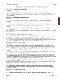
1 CHAPTER 2C. WARNING SIGNSS ection Function of WARNING SignsSupport: WARNING SIGNS call attention to unexpected conditions on or adjacent to a highway or street and to situationsthat might not be readily apparent to road users. WARNING SIGNS alert road users to conditions that might call for areduction of speed or an action in the interest of safety and efficient traffic Application of WARNING SignsStandard:The use of WARNING SIGNS shall be based on an engineering study or on engineering :The use of WARNING SIGNS should be kept to a minimum as the unnecessary use of WARNING SIGNS tends tobreed disrespect for all SIGNS . In situations where the condition or activity is seasonal or temporary, the warningsign should be removed or covered when the condition or activity does not :The categories of WARNING SIGNS are shown in Table 2C-1. WARNING SIGNS specified herein cover most of the conditions that are likely to be encountered.
2 Additionalwarning SIGNS for low-volume roads (as defined in Section ), temporary traffic control zones, school areas,highway-rail grade crossings, bicycle facilities, and highway-light rail transit grade crossings are discussed inParts 5 through 10, :Word message WARNING SIGNS other than those specified in this Manual may be developed and installed byState and local highway Design of WARNING SignsStandard:All WARNING SIGNS shall be diamond-shaped (square with one diagonal vertical) with a black legend andborder on a yellow background unless specifically designated otherwise. WARNING SIGNS shall be designedin accordance with the sizes, shapes, colors, and legends contained in the Standard Highway SIGNS book(see Section ).Option: WARNING SIGNS regarding conditions associated with pedestrians, bicyclists, playgrounds, school buses, andschools may have a black legend and border on a yellow background or a black legend and border on afluorescent yellow-green Size of WARNING SignsStandard:The sizes for WARNING SIGNS shall be as shown in Table :The Conventional Road size should be used on conventional Freeway and Expressway sizes should be used for higher-speed applications to provide larger SIGNS forincreased visibility and.
3 The Minimum size may be used on low-speed roadways where the reduced legend size would be adequatefor the WARNING or where physical conditions preclude the use of the other SIGNS and larger sizes may be used for those special applications where speed, volume, or otherfactors result in conditions where increased emphasis, improved recognition, or increased legibility would :The minimum size for supplemental WARNING plaques shall be as shown in Table : SIGNS larger than those shown in Tables 2C-2 and 2C-3 may be used (see Section ).2003 EditionPage 2C-1 Sect. to 2C-22003 EditionSect. Group Section SIGNS MUTCD , Curve, Reverse Turn,W1-1 through W1-5, W1-11,Reverse Curve, Winding Road,W1-15 Hairpin Curve, 270-Degree HorizontalW1-1a, W1-2aAlignment/Advisory HorizontalW1-10 Arrow (one direction) , W7-1a, Escape RampW7-4, Blocks Bridge, One Lane BridgeW5-2, Road, Divided RoadW6-1, W6-2, W12-1 Ends, Double End, No OutletW14-1, W14-1a, W14-2, ClearanceW12-2, , Dip, Speed HumpW8-1, W8-2, , W8-9, W8-9a When Ices Before Ahead, Yield Ahead,W3-1, W3-2, W3-3, W3-4,Signal Ahead, Be Prepared To Stop,W3-5, W3-5aSpeed , Lane Ends, Added Lane,W4-1, W4-2, W4-3, W4-5,Two-Way Traffic, Right Lane Ends,W4-6, W6-3, W9-1, Lane Ends Merge Left, W9-2, W14-3No Passing SpeedW13-2, W13-3, Road, Side Road, T, Y, andW2-1 through W2-6 Circular Arrow (two directions) Extended Green W25-1, Crossing, Truck (symbol)
4 ,W8-6, W11-1, W11-5,Emergency Vehicle, Tractor, W11-5a, W11-8, W11-10,Bicycle, Golf Cart,W11-11, W11-12p, W11-14 Horse-Drawn , Deer, Cattle,W11-2, W11-3, W11-4,Snowmobile, Horse, W11-6, W11-7, W11-9, Wheelchair, PlaygroundW15-1 Feet, XX Miles, Next XX Feet,W16-2, W16-3, W16-4,Next XX Arrow, Directional Arrow,W16-5p, W16-6p, W16-7pDiagonal Use Low Gear, X% GradeW7-2, Street Traffic Does Not The CircleW16-12pChangesinHorizontalAlignmen tVerticalAlignmentCrossSectionRoadwaySur faceConditionAdvanceTrafficControlTraffi cFlowChange inSpeedIntersectionsVehicularTrafficNonv ehicularDistanceSpeedArrowHill-RelatedSt reet NamePlaqueIntersectionShare TheRoadHOVP hoto EnforcedRoadwayRelatedTrafficRelatedSupp lementalPlaquesTable 2C-1. Categories of WARNING SignsTraffic Circle2003 EditionPage 2C-3 Sect. SeriesMinimumConventionalRoadExpress-way OversizedFreewayW1, W2, W7,W8, W9, W11,W14, W15-1,W17-1600 x 600(24 x 24)750 x 750(30 x 30)900 x 900(36 x 36)W1 Combination,W3, W4, W5,W6, W8-3,W10, W12 750 x 750(30 x 30)900 x 900(36 x 36)1200 x1200(48 x 48)1200 x 1200(48 x 48)1200 x1200(48 x 48)____DiamondW1 - Arrows900 x 450(36 x 18)1200 x 600(48 x 24)_____1500 x 750(60 x 30) W1 - Chevron300 x 450(12 x 18)450 x 600(18 x 24)750 x 900(30 x 36)900 x1200(36 x 48)____W7-41950 x 1200(78 x 48)_____W7-4b, 4c____1950 x 1500(78 x 60)____W12-2p____2100 x 600(84 x 24)____W13-2, 3, 5,W25600 x 750(24 x 30)600 x 750(24 x 30)900 x1200(36 x 48)1200 x1500(48 x 60)1200 x1500(48 x 60)RectangularPennantW14-3750 x 1000x 1000(30 x 40 x40)900 x 1200x 1200(36 x 48 x48)_____Notes: 1.
5 Larger SIGNS may be used when appropriate2. Dimensions are shown in millimeters followed by inches in parentheses and are shown as width x height1200 x 1600x 1600(48 x 64 x64)Table 2C-2. WARNING sign SizesDescriptionCircularW10-1750 (30) (48) (36) (48) x 1200(78 x 48)1950 x 1500(78 x 60)2100 x 600(84 x 24)1950 x 1200(78 x 48)1950 x 1500(78 x 60)2100 x 600(84 x 24)W10-9, 10600 x 450(24 x 18)_____Section Placement of WARNING SignsSupport:For information on placement of WARNING SIGNS , see Sections to total time needed to perceive and complete a reaction to a sign is the sum of the times necessary forPerception, Identification (understanding), Emotion (decision making), and Volition (execution of decision),and is called the PIEV time. The PIEV time can vary from several seconds for general WARNING SIGNS to 6seconds or more for WARNING SIGNS requiring high road user 2C-4 lists suggested sign placement distances for two conditions.
6 This table is provided as an aidfor determining WARNING sign 2C-42003 EditionSect. to 2C-3. Minimum Size of Supplemental WARNING PlaquesSize of Supplemental PlaqueRectangularSize of WARNING SignNotes: 1. Larger supplemental plaques may be used when appropriate2. Dimensions are shown in millimeters followed by inches in parentheses and are shown as width x height 1 Line2 LinesArrowSquare600 x 600 (24 x 24)750 x 750 (30 x 30)600 x 300 (24 x 12)600 x 450 (24 x 18)750 x 600 (30 x 24)600 x 300 (24 x 12)450 x 450 (18 x 18)600 x 600 (24 x 24)750 x 450 (30 x 18)750 x 450 (3 0 x 18)900 x 900 (36 x 36)1200 x1200 (48 x 48)Guidance: WARNING SIGNS should be placed so that they provide adequate PIEV time. The distances contained in Table2C-4 are for guidance purposes and should be applied with engineering judgment. WARNING SIGNS should not beplaced too far in advance of the condition, such that drivers might tend to forget the WARNING because of otherdriving distractions, especially in urban spacing between WARNING SIGNS with different messages should be based on the estimated PIEV time for driver comprehension of and reaction to the second effectiveness of the placement of WARNING SIGNS should be periodically evaluated under both day andnight : WARNING SIGNS that advise road users about conditions that are not related to a specific location, such as DeerCrossing or SOFT SHOULDER, may be installed in an appropriate location, based on engineering judgment,since they are not covered in Table Horizontal Alignment SIGNS (W1-1 through W1-5, W1-11, W1-15)Option.
7 The horizontal alignment Turn (W1-1), Curve (W1-2), Reverse Turn (W1-3), Reverse Curve (W1-4), orWinding Road (W1-5) SIGNS (see Figure 2C-1) may be used in advance of situations where the horizontalroadway alignment changes. A One-Direction Large Arrow (W1-6) sign (see Figure 2C-1 and Section )may be used on the outside of the turn or the change in horizontal alignment is 135 degrees or more, the Hairpin Curve (W1-11) sign (see Figure2C-1) may be the change in horizontal alignment is approximately 270 degrees, such as on a cloverleaf interchangeramp, the 270-degree Loop (W1-15) sign (see Figure 2C-1) may be :The application of these SIGNS should conform to Table the Hairpin Curve sign or the 270-degree Loop sign is installed, either a One-Direction Large Arrow(W1-6) sign or Chevron Alignment (W1-8) SIGNS should be installed on the outside of the turn or :An Advisory Speed (W13-1) plaque (see Section ) may be used to indicate the speed for the change inhorizontal alignment.
8 The supplemental distance plaque NEXT XX km (NEXT XX MILES) (W7-3a) may beinstalled below the Winding Road sign where continuous roadway curves exist (see Section ). Thecombination Horizontal Alignment/Advisory Speed sign (see Section ), combination HorizontalAlignment/Intersection sign (see Section ), or the Curve Speed sign (see Section ) may also be EditionPage 2C-5 Sect. 2C-4. Guidelines for Advance Placement of WARNING SIGNS (Metric Units)1 The distances are adjusted for a sign legibility distance of 50 m for Condition A. The distances forCondition B have been adjusted for a sign legibility distance of 75 m, which is appropriate for an align-ment WARNING symbol conditions are locations where the road user must use extra time to adjust speed and changelanes in heavy traffic because of a complex driving situation. Typical SIGNS are Merge and Right LaneEnds.
9 The distances are determined by providing the driver a PIEV time of to seconds for vehi-cle maneuvers (2001 AASHTO Policy, Exhibit 3-3, Decision Sight Distance, Avoidance Maneuver E)minus the legibility distance of 50 m for the appropriate condition is the WARNING of a potential stop situation. Typical SIGNS are Stop Ahead, Yield Ahead,Signal Ahead, and Intersection WARNING SIGNS . The distances are based on the 2001 AASHTO Policy,Stopping Sight Distance, Exhibit 3-1, providing a PIEV time of seconds, a deceleration rate of , minus the sign legibility distance of 50 conditions are locations where the road user must decrease speed to maneuver through thewarned condition. Typical SIGNS are Turn, Curve, Reverse Turn, or Reverse Curve. The distance is deter-mined by providing a second PIEV time, a vehicle deceleration rate of 3 m/second2, minus the signlegibility distance of 75 suggested distances are provided for these speeds, as the placement location is dependent on siteconditions and other signing to provide an adequate advance WARNING for the : N/A5N/A530 m40 m90 m120 m160 m200 m N/A5N/A5N/A570 m110 m140 m180 m N/A5N/A560 m90 m130 m170 m N/A540 m70 m110 m150 mAdvance Placement Distance 1 Posted or 85th-PercentileSpeed(km/h)Condition A:SpeedReduction andLane Changingin HeavyTraffic2 Condition B.
10 Deceleration to the listed advisoryspeed (km/h) for the condition4102030405060708030405060708090 10011012013060 m100 m150 m180 m220 m260 m310 m350 m380 m420 m460 mN/A5N/A5N/A530 m50 m80 m110 m130 m170 m200 m230 m N/A5N/A5N/A5N/A540 m60 m90 m120 m160 m190 m230 mN/A5N/A530 m55 m80 m115m150 m185 m230 mN/A550 m70 m110 m140 m180 m220 mN/A5N/A5 N/A5N/A5N/A5 N/A5N/A5N/A540 m60 m100 m130 m170 m210 m03 N/A550 m90 m120 m90 N/A560 m100 m100 40 m70 m110 Page 2C-62003 EditionSect. N/A5 Table 2C-4. Guidelines for Advance Placement of WARNING SIGNS (English Units)Advance Placement Distance 1 Posted or 85th-PercentileSpeedCondition A:Speed reduc-tion and lanechanging inheavy traffic2 Condition B: Deceleration to the listed advisoryspeed (mph) for the condition41020304050 Notes:20 mph25 mph30 mph35 mph40 mph45 mph50 mph55 mph60 mph65 mph70 mph75 mph225 ft325 ft450 ft550 ft650 ft750 ft850 ft950 ft1100 ft1200 ft1250 ft1350 ftN/A5N/A5N/A5N/A5125 ft175 ft250 ft325 ft400 ft475 ft550 ft650 ftN/A5N/A5N/A5N/A5N/A5125 ft200 ft275 ft350 ft425 ft525 ft625 ftN/A5N/A5N/A5N/A5150 ft225 ft300 ft400 ft500 ft600 ftN/A5N/A5100 ft175 ft250 ft350 ft425 ft525 ftN/A5100 ft175 ft275 ft350 ft450 ftN/A5175 ft250 ft350 ft N/A5 N/A5 N/A51 The distances are adjusted for a sign legibility distance of 175 ft for Condition A.