Transcription of CHAPTER 3 INDUCTION MOTOR AND DIFFERENT …
1 57 CHAPTER 3 INDUCTION MOTOR AND DIFFERENT speed control methods Page No Introduction 58 three Phase INDUCTION MOTOR 58 Stator 60 Rotor 60 Working principle of three phase INDUCTION MOTOR 62 Equivalent Circuit 63 Slip 65 DIFFERENT speed control methods 66 Stator voltage control method 66 Frequency control method 68 Volts Hertz (V/F) control method 68 Conclusion 71 58 CHAPTER 3 INDUCTION MOTOR AND DIFFERENT speed control methods Introduction This CHAPTER describes the construction, principal of operation, start up consideration and the basic speed control methods for INDUCTION MOTOR .
2 three Phase INDUCTION MOTOR (IM) The three -phase INDUCTION motors are also called as asynchronous motors, which are most commonly used type of MOTOR in industrial applications. In particular, the squirrel-Cage INDUCTION motors are widely used electric MOTOR in home and industrial applications, because these machines are very economical, rugged and reliable. They are available in the ranges of Fractional Horse Power (FHP) to multi-megawatt capacity. Fractional Horse Power motors are available in single-phase as well as poly-phase ( three -phase).
3 The three phase machines are used most often in variable- speed drives where the torque requirement is more. An INDUCTION MOTOR or asynchronous MOTOR is a type of alternating current MOTOR where power is supplied to rotor by means of electromagnetic INDUCTION . An electric MOTOR rotates because of magnetic force exerted between a stationary electromagnet called the stator and rotating electromagnet called the rotor. The current in stator side creates an electromagnetic field which interacts with the secondary to produce a resultant torque, transforming electrical energy into mechanical energy.
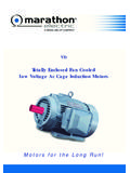
4 The cross sectional view of INDUCTION MOTOR and its various parts [4] are as shown in Fig Construction: In this section, the construction details of INDUCTION MOTOR are discussed. A three phase INDUCTION MOTOR mainly consists of two parts, stator and rotor. Stator is the stationary 59 part while the rotor is the rotating part of the MOTOR and they are separated by a small air gap depending on the rating of the MOTOR . Fig. : Squirrel-cage three -phase INDUCTION MOTOR Fig. Stator 60 Stator The stator is as shown in Fig , which consists of a steel frame which encloses a hollow cylindrical core made up of thin laminations of silicon steel to reduce eddy current and hysteresis loss.
5 A large number of uniform slots are cut on the inner periphery of the core. The stator conductors are placed in these slots which are insulated from one another and also from the slots. These conductors are connected as a balanced three phase star or delta winding. The windings are wound for a definite number of poles depending on the requirement of speed . It is wound for more number of poles, if speed required is less and vice versa. According to the relation Ns = 120f / P - - - - - - - - - - - - - - - ( ) Where Ns is the synchronous speed in RPM f is the supply frequency P is the number of poles When a three phase supply is given to stator winding a magnetic field of constant magnitude and rotating at synchronous speed is produced.
6 This rotating magnetic field is mainly responsible for producing the torque in the rotor, so that it can rotate at the rated speed . Rotor The rotor is the rotating part of the INDUCTION MOTOR and is mounted on the shaft of the MOTOR to which any mechanical load can be connected. Based on the construction of the rotor, INDUCTION motors are broadly classified in two categories; squirrel cage motors and slip ring motors. The stator construction is the same in both motors. 61 Squirrel cage motors: Fig. : Squirrel cage type rotor Almost 90% of INDUCTION motors are squirrel cage motors.
7 This is because the squirrel cage MOTOR has a simple and rugged construction. Fig shows the squirrel cage type rotor, it consists of cylindrical laminated core with axially placed parallel slots for carrying rotor conductors. The rotor conductors are heavy bars of copper or aluminium. Each slot carries a copper, aluminium or alloy bar. If the slots are semi closed, then these bars are inserted from the ends. These rotor bars are permanently short-circuited at both ends by means of the end rings, thus short circuiting themselves at both the ends.
8 As rotor bars are short circuited on themselves, it is not possible to add any external resistance in series with rotor circuit during starting. The slots are slightly skewed, which helps in two ways It reduces noise due to magnetic hum and makes MOTOR run quietly. It reduces locking tendency between rotor and stator. Advantages of squirrel cage rotor: 1. It is simple in construction, rugged and can withstand rough handling. 62 2. Maintenance cost is low. 3. It has better efficiency and power factor. 4. A simple star delta starter is sufficient to start the rotor.
9 5. It is explosion proof as there are no slip rings and brushes. Slip ring motors: In the slip ring MOTOR , the windings on the rotor are terminated to three insulated slip rings mounted on the shaft with brushes resting on them. This allows an introduction of an external resistor to the rotor winding. The external resistor can be used to boost the starting torque of the MOTOR and change the speed -torque characteristic. When running under normal conditions, the slip rings are short-circuited, using an external metal collar, which is pushed along the shaft to connect the rings.
10 In normal conditions, the slip ring MOTOR functions like a squirrel cage MOTOR . Working principle of three phase INDUCTION MOTOR When a three phase supply is given to the three phase stator winding, a magnetic field of constant magnitude and rotating at synchronous speed Ns is produced. This rotating magnetic field sweeps across the rotor conductors and hence an electromagnetic force (EMF) is induced in rotor conductors. As the rotor conductors are short circuited on themselves the induced EMF sets up a current in the rotor conductors in such a direction as to produce a torque, which rotates the rotor in same direction as magnetic field so that relative speed decreases.