Transcription of Chapter 3: Resistive Network Analysis Instructor …
1 G. Rizzoni, fundamentals of electrical engineering , 1st Edition Problem solutions, Chapter 3 PROPRIETARY MATERIAL. The McGraw-Hill Companies, Inc. Limited distribution permitted only to teachers and educators for course preparation. If you are a student using this Manual, you are using it without permission. Chapter 3: Resistive Network Analysis Instructor Notes Chapter 3 presents the principal topics in the Analysis of Resistive (DC) circuits. The presentation of node voltage and mesh current Analysis is supported by several solved examples and drill exercises, with emphasis placed on developing consistent solution methods, and on reinforcing the use of a systematic approach.
2 The aim of this style of presentation, which is perhaps more detailed than usual in a textbook written for a non-majors audience, is to develop good habits early on, with the hope that the orderly approach presented in Chapter 3 may facilitate the discussion of AC and transient Analysis in Chapters 4 and 5. Make The Connection sidebars (pp. 65-67) introduce analogies between electrical and thermal circuit elements. These analogies are to be encountered again in Chapter 5. A brief discussion of the principle of superposition precedes the discussion of Th venin and Norton equivalent circuits.
3 Again, the presentation is rich in examples and drill exercises, because the concept of equivalent circuits will be heavily exploited in the Analysis of AC and transient circuits in later chapters. The Focus on Methodology boxes (p. 66 Node Analysis ; p. 76 Mesh Analysis ; pp. 93, 97, 101 Equivalent Circuits) provide the student with a systematic approach to the solution of all basic Network Analysis problems. Following a brief discussion of maximum power transfer, the Chapter closes with a section on nonlinear circuit elements and load-line Analysis .
4 This section can be easily skipped in a survey course, and may be picked up later, in conjunction with Chapter 9, if the Instructor wishes to devote some attention to load-line Analysis of diode circuits. Finally, those instructors who are used to introducing the op-amp as a circuit element, will find that sections and can be covered together with Chapter 3, and that a good complement of homework problems and exercises devoted to the Analysis of the op-amp as a circuit element is provided in Chapter 8.
5 Modularity is a recurrent feature of this book, and we shall draw attention to it throughout these Instructor Notes. The homework problems present a graded variety of circuit problems. Since the aim of this Chapter is to teach solution techniques, there are relatively few problems devoted to applications. We should call the Instructor 's attention to the following end-of- Chapter problems: on the Wheatstone bridge; and on fuses; on electrical power distribution systems; on various nonlinear resistance devices.
6 The Chapter includes 83 problems, as well as 25 fully solved exercises. Learning Objectives for Chapter 3 1. Compute the solution of circuits containing linear resistors and independent and dependent sources using node Analysis . 2. Compute the solution of circuits containing linear resistors and independent and dependent sources using mesh Analysis . 3. Apply the principle of superposition to linear circuits containing independent sources. 4. Compute Th venin and Norton equivalent circuits for networks containing linear resistors and independent and dependent sources.
7 5. Use equivalent circuits ideas to compute the maximum power transfer between a source and a load. 6. Use the concept of equivalent circuit to determine voltage, current and power for nonlinear loads using load-line Analysis and analytical methods. G. Rizzoni, fundamentals of electrical engineering , 1st Edition Problem solutions, Chapter 3 PROPRIETARY MATERIAL. The McGraw-Hill Companies, Inc. Limited distribution permitted only to teachers and educators for course preparation. If you are a student using this Manual, you are using it without permission.
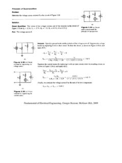
8 Sections , , , : Nodal and Mesh Analysis Problem Note: the rightmost top resistor missing a value should be 1 . Solution: Known quantities: Circuit shown in Figure Find: Voltages and . Analysis : Applying KCL at each of the two nodes, we obtain the following equations: Rearranging the equations, Solving the equations, and Focus on Methodology: Node Voltage Analysis Method 1. Select a reference node(usually ground). This node usually has most elements tied to it. All other nodes will be referenced to this node.
9 2. Define the remaining n 1 node voltages as the independent or dependent variables. Each of the m voltage sources in the circuit will be associated with a dependent variable. If a node is not connected to a voltage source, then its voltage is treated as an independent variable. 3. Apply KCL at each node labeled as an independent variable, expressing each current in terms of the adjacent node voltages. 4. Solve the linear system of n 1 m unknowns. Focus on Methodology: Mesh Current Analysis Method 1. Define each mesh current consistently.
10 Unknown mesh currents will be always defined in the clockwise direction; known mesh currents ( , when a current source is present) will always be defined in the direction of the current source. 2. In a circuit with n meshes and m current sources, n m independent equations will result. The unknown mesh currents are the n m independent variables. 3. Apply KVL to each mesh containing an unknown mesh current, expressing each voltage in terms of one or more mesh 4. Solve the linear system of n m unknowns. G. Rizzoni, fundamentals of electrical engineering , 1st Edition Problem solutions, Chapter 3 PROPRIETARY MATERIAL.