Transcription of Electrical Engineering Fundamentals - Amazon S3
1 A SunCam online continuing education course Electrical Engineering Fundamentals for Non- Electrical Engineers by Brad Meyer, PE Electrical Engineering Fundamentals for Non- Electrical Engineers A SunCam online continuing education course Copyright 2014 Brad Meyer, PE Page 2 of 36 Contents Introduction .. 3 Definitions .. 3 Power Sources .. 4 Series vs. Parallel .. 9 Current Behavior at a Node .. 9 Resistors ..10 Combining Resistors in Series and Parallel Circuits ..11 Capacitors ..14 Capacitor Behavior While Charging ..14 Capacitor Behavior While Discharging ..16 Inductors ..18 Inductor Behavior While Charging ..19 Inductor Behavior While Discharging.
2 21 Imaginary Impedance ..24 Total Impedance Example ..28 Applying Ohm s Law to Complex Circuits ..30 Kirchoff s Laws ..32 Summary ..36 Electrical Engineering Fundamentals for Non- Electrical Engineers A SunCam online continuing education course Copyright 2014 Brad Meyer, PE Page 3 of 36 Introduction We all interact with electricity on a daily basis. Most of us start off the day waking up to an alarm clock, then we turn on the lights, take a hot shower, and make a cup of coffee, etc. Electricity is engrained in our daily lives, from the electricity in the wall sockets to power our alarm clocks and coffee pots, to the electricity wired in the ceiling for lights and a bathroom fan, to the heater elements in an electric water heater.
3 It is easy to take electricity for granted, but we truly appreciate it when the power goes out for a few hours. That s when we realize that we have lost our TV, air conditioners, refrigerators, and the children go into panic mode with a loss of the internet and social media. Electrical Engineering Fundamentals for Non- Electrical Engineers is a course designed to promote an understanding of the Fundamentals of electricity. The course covers the differences between Alternating Current (AC) and Direct Current (DC) power sources by explaining the behavior of the voltage and current for both types of sources. The fundamental circuit building blocks including resistors, capacitors and inductors are covered including their behavior in series and parallel circuits as well as transient analysis.
4 The course covers Ohm s law and Kirchoff s Laws and their application to performing circuit analysis. This course also includes a brief introduction to imaginary numbers and phasors as related to current, voltage, and impedance. Definitions x Alternating Current (AC) Current flowing from a source that can be represented by a sine wave, which results in current flowing both directions. x Amperes or Amps (A) The amount of charge flowing past a given point per unit time. 1 Amp = 1 Coulomb / second x Coulomb (C) SI unit of charge x Cycles Number of times a complete sine wave occurs. x Direct Current (DC) Current flowing from a source which does not change polarity, which results in current flowing in only one direction.
5 X Farad (F) SI unit of capacitance. x Henry (H) SI unit of inductance. x Hertz (Hz) SI unit of frequency. x Joules (J) SI unit of energy. Electrical Engineering Fundamentals for Non- Electrical Engineers A SunCam online continuing education course Copyright 2014 Brad Meyer, PE Page 4 of 36 x Ohms ( ) SI unit of resistance. x RMS Root Mean Square value x SI International System of Units x Volts (V) A measure of the difference in Electrical potential between two points. x Watts (W) SI unit of power. Power Sources Let s start with some of the fundamental building blocks.
6 Every circuit needs a power source. There are two basic types of power sources, Alternating Current (AC) and Direct Current (DC). Alternating current, as the name implies, changes the polarity of the source at some frequency. Direct current maintains the same polarity; therefore, the positive and negative terminals are always at the same location. Figure 1 shows a standard symbol for an AC source. Figure 2 shows two standard symbols for a DC source. AC Figure 1 Alternating Current (AC) Source DC Figure 2 Direct Current (DC) Sources Examples of an AC source could be a generator or a wall outlet in your house. Examples of a DC source could be a car battery or simple AA battery.
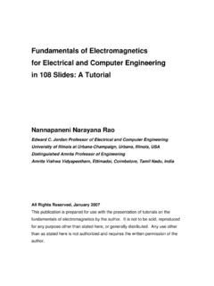
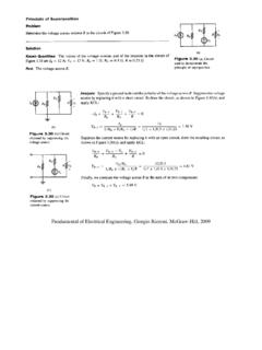
7 So what is the difference between AC and DC? It may best be illustrated in the examples below. Figure 3 shows a simple DC circuit. Figure 4 shows that the voltage of the 12 VDC source. Figure 5 shows the current through the 12 resistor. Electrical Engineering Fundamentals for Non- Electrical Engineers A SunCam online continuing education course Copyright 2014 Brad Meyer, PE Page 5 of 36 12V DC12 ohmsCurrent Figure 3 Simple DC Circuit Figure 4 Voltage vs Time for an ideal DC source Figure 5 Current vs Time for an ideal DC source In Figure 3 Simple DC Circuit, current leaves the positive terminal (+) of the 12 Volt DC source, flows through the 12 Ohm ( ) resistor, and then returns to the negative terminal (-) of the 12V DC source.
8 In an ideal voltage source, there is no change in voltage over time due to temperature, load, or internal battery resistance. Figure 4 Voltage vs Time for an ideal DC source shows that the voltage of 12 V source is constant with time. Figure 5 Current vs Time for an ideal DC source shows that the current through the resistor is constant with time. Note: There are two conventions for current flow. (1) Conventional flow assumes that current flows from the positive terminal (+) to the negative terminal (-). This is also called hole flow. (2) Electron flow assumes current flows from the negative terminal (-) to the 024681012140246810 Voltage (V)Time (s)Voltage vs (A)Time (s)Current vs Electrical Engineering Fundamentals for Non- Electrical Engineers A SunCam online continuing education course Copyright 2014 Brad Meyer, PE Page 6 of 36 positive terminal (+).
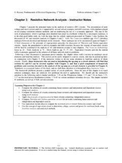
9 This is the path of the flowing electrons. For simplicity, conventional flow will be used in all examples. Figure 5 was developed using a relationship called Ohm s Law. Ohm s law states that in a circuit containing only linear components, the expression that governs the relationship between voltage, current, and resistance is: Where: V is the voltage measured in volts (V) I is the current measured in amps (A) R is the resistance measured in ohms ( ) Note: An example of a non-linear component is a light bulb that varies the resistance with temperature. In an Alternating Current (AC) circuit, we see a much different behavior. Figure 6 shows a simple AC circuit when the voltage of the source is greater than zero.
10 Figure 7 shows the voltage vs. time for the AC source and the RMS value for voltage. Figure 8 shows the simple AC circuit when the voltage of the source is less than zero. Figure 9 shows the current vs. time for the current flowing through the 12 resistor. Electrical Engineering Fundamentals for Non- Electrical Engineers A SunCam online continuing education course Copyright 2014 Brad Meyer, PE Page 7 of 36 12 ohmsACCurrent+_ Figure 6 Simple AC Circuit when V>0 Figure 7 Voltage vs Time for an AC source 12 ohmsACCurrent+_ Figure 8 Simple AC Circuit when V<0 Figure 9 Current vs Time for an AC source As seen in Figure 6, current leaves the positive terminal of the 12 Volt AC source, flows through the 12 Ohm ( ) resistor, and then returns to the negative terminal of the 12V AC source.