Transcription of CHAPTER 4 EARTH PRESSURE THEORY AND APPLICATION
1 CHAPTER 4 EARTH PRESSURE THEORY AND APPLICATION EARTH PRESSURE THEORY AND APPLICATION GENERAL All shoring systems shall be designed to withstand lateral EARTH PRESSURE , water PRESSURE and the effect of surcharge loads in accordance with the general principles and guidelines specified in this Caltrans Trenching and Shoring Manual. SHORING TYPES Shoring systems are generally classified as unrestrained (non-gravity cantilevered), and restrained (braced or anchored). Unrestrained shoring systems rely on structural components of the wall partially embedded in the foundation material to mobilize passive resistance to lateral loads. Restrained shoring systems derive their capacity to resist lateral loads by their structural components being restrained by tension or compression elements connected to the vertical structural members of the shoring system and, additionally, by the partial embedment (if any) of their structural components into the foundation material.
2 Unrestrained Shoring Systems Unrestrained shoring systems (non-gravity cantilevered walls) are constructed of vertical structural members consisting of partially embedded soldier piles or continuous sheet piles. This type of system depends on the passive resistance of the foundation material and the moment resisting capacity of the vertical structural members for stability; therefore its maximum height is limited by the competence of the foundation material and the moment resisting capacity of the vertical structural members. The economical height of this type of wall is generally limited to a maximum of 18 feet. Restrained Shoring Systems Restrained Shoring Systems are either anchored or braced walls.
3 They are typically comprised of the same elements as unrestrained (non-gravity cantilevered) walls, but derive additional lateral resistance from one or more levels of braces, rakers, or anchors. These walls are typically constructed in cut situations in which construction proceeds from the top down to the base of the wall. The vertical wall elements should extend below the potential failure plane associated with the retained soil mass. For these types of walls, economical wall heights up to 80 feet are feasible. 4-1 p CT TRENCHING AND SHORING MANUAL Note - Soil Nail Walls and Mechanically Stabilized EARTH (MSE) Walls are not included in this Manual. Both of these types of systems are designed by other methods that can be found on-line with FHWA or AASHTO.
4 LOADING A major issue in providing a safe shoring system design is to determine the appropriate EARTH PRESSURE loading diagram. The loads are to be calculated using the appropriate EARTH PRESSURE theories. The lateral horizontal stresses ( ) for both active and passive PRESSURE are to be calculated based on the soil properties and the shoring system. EARTH PRESSURE loads on a shoring system are a function of the unit weight of the soil, location of the groundwater table, seepage forces, surcharge loads, and the shoring structure system. Shoring systems that cannot tolerate any movement should be designed for at-rest lateral EARTH PRESSURE . Shoring systems which can move away from the soil mass should be designed for active EARTH PRESSURE conditions, depending on the magnitude of the tolerable movement.
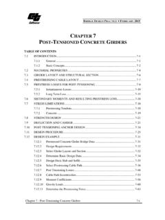
5 Any movement, which is required to reach the minimum active PRESSURE or the maximum passive PRESSURE , is a function of the wall height and the soil type. Significant movement is necessary to mobilize the full passive PRESSURE . The variation of lateral stress between the active and passive EARTH PRESSURE values can be brought about only through lateral movement within the soil mass of the backfill as shown in Figure 4-1. Ultimate PassiveUltimate Passive Away from the backfillToward the backfillDisplacementActiveAt RestPaPoPp p>> aPassive aAway from the backfill Toward the backfill Displacement Active At Rest Pa Po Pp p>> aPassive a p Figure 4-1. Active and passive EARTH PRESSURE coefficient as a function of wall displacement 4-2 EARTH PRESSURE THEORY AND APPLICATION Typical values of these mobilizing movements, relative to wall height, are given in Table 4-1 (Clough 1991).
6 Table 4-1. Mobilized Wall Movements Type of Backfill Value of /H Active Passive Dense Sand Medium Dense Sand Loose Sand Compacted Silt Compacted Lean Clay Compacted Fat Clay where: = the movement of top of wall required to reach minimum active or maximum passive PRESSURE , by tilting or lateral translation, and H = height of wall. 4-3 CT TRENCHING AND SHORING MANUAL GRANULAR SOIL At present, methods of analysis in common use for retaining structures are based on Rankine (1857) and Coulomb (1776) theories. Both methods are based on the limit equilibrium approach with an assumed planar failure surface. Developments since 1920, largely due to the influence of Terzaghi (1943), have led to a better understanding of the limitations and appropriate applications of classical EARTH PRESSURE theories.
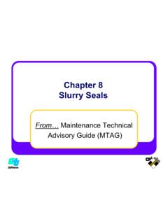
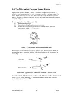
7 Terzaghi assumed a logarithmic failure surface. Many experiments have been conducted to validate Coulomb s wedge THEORY and it has been found that the sliding surface is not a plane, but a curved surface as shown in Figure 4-2 (Terzaghi 1943). Curve Surface Plane Surface Figure 4-2. Comparison of Plane versus Curve Failure Surfaces Furthermore, these experiments have shown that the Rankine (1857) and Coulomb (1776) EARTH PRESSURE theories lead to quite accurate results for the active EARTH PRESSURE . However, for the passive EARTH PRESSURE , these theories are accurate only for the backfill of clean dry sand for a low wall interface friction angle. For the purpose of the initial discussion, it is assumed that the backfills are level, homogeneous, isotropic and distribution of vertical stress ( v) with depth is hydrostatic as shown in Figure 4-3.
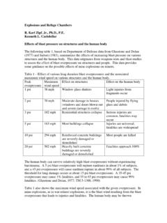
8 4-4 h = v K = h K P = 1 2 h h EARTH PRESSURE THEORY AND APPLICATION The horizontal stress ( h) is linearly proportional to depth and is a multiple of vertical stress ( v) as shown in. Eq. 4-1. Eq. 4-1 Eq. 4-2 Depending on the wall movement, the coefficient K represents active (Ka), passive (Kp) or at-rest (Ko) EARTH PRESSURE coefficient in the above equation. The resultant lateral EARTH load, P, which is equal to the area of the load diagram, shall be assumed to act at a height of h/3 above the base of the wall, where h is the height of the PRESSURE surface, measured from the surface of the ground to the base of the wall. P is the force that causes bending, sliding and overturning in the wall.
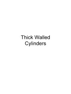
9 Figure 4-3. Lateral EARTH PRESSURE Variation with Depth Depending on the shoring system the value of the active and/or passive PRESSURE can be determined using either the Rankine, Coulomb, Log Spiral and Trial Wedge methods. The state of the active and passive EARTH PRESSURE depends on the expansion or compression transformation of the backfill from elastic state to state of plastic equilibrium. The concept of the active and passive EARTH PRESSURE THEORY can be explained using a continuous deadman near the 4-5 CT TRENCHING AND SHORING MANUAL ground surface for the stability of a sheet pile wall as shown in Figure 4-4. As a result of wall deflection, , the tie rod is pulled until the active and passive wedges are formed behind and in front of the deadman.
10 Element P, in the front of the deadman and element A, at the front of the deadman are acted on by two principal stresses, a vertical stress ( v) and horizontal stress ( h). In the active case, the horizontal stress ( a) is the minor principal stress and the vertical stress ( v) is the major principal stress. In the passive case, the horizontal stress ( p) is the major principal stress and the vertical stress ( v) is the minor principal stress. The resulting failure surface within the soil mass corresponding to active and passive EARTH PRESSURE for the cohesionless soil is shown in Figure 4-4. 4-6 O EARTH PRESSURE THEORY AND APPLICATION Sheet Pile wall Tierod AP O Figure 4-4.