Transcription of Chapter 4 Open-Channel Flow
1 Hydraulics Manual M Page 4-1 March 2022 4-1 Introduction An open channel is a watercourse that allows part of the flow to be exposed to the atmosphere. This type of channel includes rivers, culverts, stormwater systems that flow by gravity, roadside ditches, and roadway gutters. Open-Channel flow design criteria are used in the following areas of transportation design: River stabilization (Section 4-6) Partially full flow pipes Roadside ditches (Section 4-3) Bridge design Downstream analysisProper design requires that open channels have sufficient hydraulic capacity to convey the flow of the design storm. In the case of earth-lined channels or river channels, bank protection is also required if the shear stress is high enough to cause erosion or scouring. This Chapter provides guidance for designing systems with Open-Channel flow, including determining design velocity (Section 4-2) and critical depth (Section 4-4), designing roadside ditches (Section 4-3), and conducting backwater analysis for river flow (Section 4-5).
2 River stabilization (Section 4-6) may be necessary for highly erosive, high-energy rivers, to help the river dissipate some of its energy and stabilize the riverbanks and channel bottom. The success of the rock structures or rock bank protection is dependent on the ability of the rock to withstand the forces of the river; therefore, it is important to properly size the rocks used. The methodology for sizing rocks used in river stabilization is described in HEC-23 Volume 1 and Volume 2. The flow capacity of a culvert is often dependent on the channel upstream and downstream from that culvert. For example, the tailwater level is often controlled by the hydraulic capacity of the channel downstream of the culvert. Knowing the flow capacity of the downstream channel , Open-Channel flow equations can be applied to a channel cross section to adequately determine the depth of flow in the downstream channel . This depth can then be used in the analysis of the culvert hydraulic capacity.
3 Biofiltration swales are shallow, grass -lined, open channels that clean stormwater runoff before it reaches a receiving body. The PEO should route stormwater through biofiltration swales or other approved stormwater BMPs as required in the Highway Runoff Manual (WSDOT 2019b). A downstream analysis identifies and evaluates the impacts that a project will have on the hydraulic conveyance system downstream of the project site. See Section 1- Measurement of flow in channels can be difficult because of the non-uniform channel dimensions and variations in velocities across the channel . Weirs allow water to be routed through the structure of known dimension, permitting flow rates to be measured as a function of depth of flow through the structure. Chapter 4 Open-Channel Flow Hydraulics Manual M Page 4-2 March 2022 4- 2 Determining channel Flow Rates In Open-Channel flow, the volume of flow and the rate at which flow travels are useful in designing the channel .
4 For the purposes of the Hydraulics Manual, the determination of the flow rate in the channel , also known as discharge, is based on the continuity of flow equation or Equation 4-1. This equation states that the discharge (Q) is equivalent to the product of the channel velocity (V) and the area of flow (A). Q = V A (4-1) Where: Q = discharge, cfs V = velocity, ft/s A = flow area, ft2 When actual channel or stream velocity measurements are not available, the velocity can be calculated using the Manning s equation shown in Equation 4-2. V = (R^2/3)(S^1/2)/n (4-2) Where: V = mean velocity of flow in feet per second R = hydraulic radius in feet S = slope of the energy gradient or, for assumed uniform flow, the slope of the channel in feet (vertical) per foot (horizontal) n = Manning's roughness coefficient or friction factor of the channel lining In some situations, the flow area of a channel is known. If it is not, the flow area or flow depth must be calculated by trial and error, as presented in HDS-4, or by using computer programs.
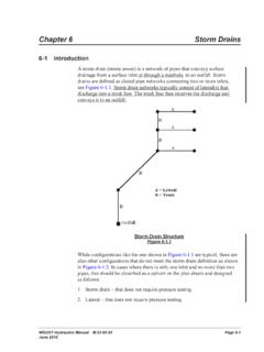
5 The PEO is also referred to HDS-4 for further information on channel flow rates and velocities. Field Slope Measurements By definition, slope is rise over run (or fall) per unit length along the channel centerline or thalweg. Slope is the vertical drop in the river channel divided by the horizontal distance measured along the thalweg of a specific reach. The vertical drop shall be measured from the water surface at the top-of-riffle (end of pool) to the next top-of-riffle to get an accurate representation of the slope in that reach (Figure 4-1). Figure 4-1 Field Slope Measurement Chapter 4 Open-Channel Flow Hydraulics Manual M Page 4-3 March 2022 4- 3 Roadside Ditch Design Criteria Roadside ditches are generally located alongside uncurbed roadways with the primary purpose of conveying runoff away from the roadway. Ditches shall be designed to convey the 10-year recurrence interval with a freeboard (from the ditch design water surface elevation to the bottom of the pavement subgrade or ditch spill) and a maximum side slope of 2 horizontal (H):1 vertical (V) (Figure 4-2).
6 The preferred cross section of a ditch is trapezoidal; however, a V ditch that meets the design requirements can also be used where ROW is limited. In those cases where the grade is flat, preventing adequate freeboard, the depth of channel should still be sufficient to remove the water without saturating the subgrade shoulder. If the freeboard is less than foot, a deviation is required, unless there is a strong justification by the designer for the RHE and Region Maintenance to allow the installation of an impermeable ditch liner or an underdrain system underneath the ditch to prevent saturation of the roadway subgrade. To maintain the integrity of the channel , ditches are usually lined. See HDS-4, HEC-15, or the Standard Specifications for more information (WSDOT 2021c). WSDOT s Design Manual also contains design guidance for both paved and grass -lined ditches (WSDOT 2020). The WSDOT Design Manual also requires a 2-foot minimum ditch depth from the edge of pavement to the bottom of the ditch (WSDOT 2020).
7 If the depth is less than 2 feet, justification shall be included in the project design documentation. A Design Manual deviation will not be required as long the Hydraulics Manual requirement is met (WSDOT 2020). Figure 4-2 Drainage Ditch Detail Ditches should not be confused with biofiltration swales. In addition to collecting and conveying drainage, biofiltration swales provide runoff treatment by filtering out sediment. (See the Highway Runoff Manual for design guidance for biofiltration swales [WSDOT 2019b].) Roadside ditches are to be designed so the integrity or geometry of the roadway is not compromised. A drainage inlet can be placed at a low point or at the end of the ditch to convey the water to its intended discharge point. Ditch inlets operate as weirs under low water depth conditions or as orifices at greater depths. Orifice flow begins at depths dependent on the grate size. flows in a transition stage could yield water depths fluctuating between weir and orifice control.
8 Ditch inlets are more susceptible to clogging from sediments and debris. Ensure that the grate is adequately sized to satisfy the ditch freeboard requirement or prevent water from spilling over onto the roadway. Contact the RHE for ditch inlet analysis. Chapter 4 Open-Channel Flow Hydraulics Manual M Page 4-4 March 2022 4- 4 Critical Depth Before finalizing a channel design, the PEO must verify that the normal depth of a channel is either greater than or less than the critical depth. If this cannot be achieved contact the RHE for additional guidance. Critical depth is the depth of water at critical flow, a very unstable condition where the flow is turbulent and a slight change in the specific energy the sum of the flow depth and velocity head could cause a significant rise or fall in the depth of flow. Critical flow is also the dividing point between the subcritical flow regime (tranquil flow), where normal depth is greater than critical depth, and the supercritical flow regime (rapid flow), where normal depth is less than critical depth.
9 Critical flow tends to occur when passing through an excessive contraction, either vertical or horizontal, before the water is discharged into an area where the flow is not restricted. A characteristic of critical depth flow is often a series of surface undulations over a very short stretch of channel . The PEO should be aware of the following areas where critical flow could occur: culverts, bridges, and near the brink of an overfall. A discussion of specific energy is beyond the scope of the Hydraulics Manual. The PEO should refer to HDS-5 or HEC-14, for further information. 4- 5 River Backwater Analysis Natural river channels tend to be highly irregular in shape so an analysis using Manning s equation, while helpful for making an approximation, is not sufficiently accurate to determine a river water surface profile. The HQ Hydraulics Section is responsible for computing water surface profiles and has several computer programs to calculate the water surface profile of natural river channels.
10 Computation of the water surface profile is called a backwater analysis. The purpose of this section is to state when a backwater analysis is necessary and to summarize the minimum design requirements for the analysis and provide the project office with a list of field information required for the HQ Hydraulics Section to perform an analysis. This section will be revised in a future update. A backwater analysis is performed when designing a bridge that crosses a river designated as a FEMA regulatory floodplain. WSDOT is required by federal mandate to design these bridges to accommodate the 100-year storm event. It is desirable to maintain a 3-foot vertical clearance between the bottom of the bridge and the 100-year water surface elevation. The water surface elevations for the 100-year and 500-year water surface profiles shall be shown on the plans. Backwater analysis can be useful in culvert design. Computing the water surface profile can help the PEO determine if the culvert is flowing under inlet or outlet control.