Transcription of Chapter 4 - Thermal Management and Packing …
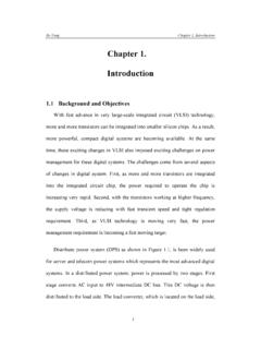
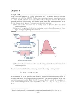
1 4. Thermal Management and Packaging Considerations1144. Thermal Management AND PACKAGING CONSIDERATIONSC hapter FourThermal Management and Packaging ConsiderationsAs the power densities of power converters continue to grow, Thermal issues arebecoming extremely important and vital for the product quality. As illustrated in Fig. (a),which shows the primary causes of failures in electronic equipment, excessive temperatures ofthe critical components, such as semiconductors and transformers, are the dominant cause ofequipment failures, as shown in Fig.
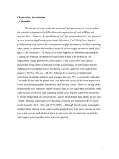
2 (b) [C1].Power systems for portable and hand-held electronic equipment are usually housed incompletely sealed enclosures due to safety reasons. Since the cooling of these systems primarilyrelies on natural convection, the effective Management of the heat removal from a sealedenclosure poses a major Thermal -design challenge. In fact, Thermal design through thermalmodeling and simulation is becoming an integral part of the design process because it is usuallyless time consuming and less expensive compared to the experimental cut-and-try Thermal Management and Packaging Considerations115 Vibration 22%Dust 6%Humidity19%Temperature54%Source:USAirF orceAvionicsIntegrity Program (AVIP)(a) Temperature ( C)Failure rate (per 100,000 hrs) : GEC Research(b)Figure of Thermal Management : (a) breakdown of premature failure causes ofelectronic equipment.
3 (b) equipment failure rate as a function of Thermal Management and Packaging Considerations116In the past, Thermal analysis has been mainly focused on component-level performance inthe free-air environment or with estimated boundary conditions [C18], [C19]. Since componentsbehave differently in a high-power-density environment due to Thermal coupling withsurrounding components, the accuracy and, therefore, the usefulness of the component-levelthermal characterization are very limited in practical high-power-density systems. In addition, theextrapolation of the Thermal -design performance from one converter structure to another is alsoof a limited value because of the possible lack of packaging similarities, different fluid velocities,and different temperature more accurate approach to Thermal analysis and modeling is the computational fluiddynamics (CFD) approach which calculates heat transfer coefficients based on actual airflowconditions [C16], [C23].
4 As an example, the CFD-based finite volume analysis (FVA) softwareFlotherm [E7], widely used in industry for modeling of electronic-equipment cooling, combinesconduction, convection, and radiation effects and solves the entire coupled problemsimultaneously. As a result, converter performance and component behavior can be simulatedand analyzed in the actual operating this Chapter , the general design aspects of the Thermal Management for high-power-density external adapters/chargers for portable electronic equipment are discussed.
5 As anexample, an off-line, 36-W flyback adapter is analyzed using CFD Thermal modeling andsimulation with Flotherm. The Thermal modeling and simulation are performed for a number ofpackaging approaches. The simulation results are verified experimentally. Finally, the designguidelines for optimum Thermal performance are Thermal Management and Packaging Power Density LimitsGenerally, in the adapters/chargers for portable electronic equipment housed in sealedenclosures, the heat generated by internally dissipated power is removed by natural convectionand radiation from the enclosure surfaces.
6 To comply with various agency requirements andinternal specifications defined by portable-equipment manufacturers, the maximum surfacetemperature of the enclosure which is accessible to the user is limited. The most commonlyencountered specification of the maximum-surface-temperature-limit is Tsurf = 75 C at ambienttemperature Tamb = 40 C, , the maximum allowable surface-temperature rise above theambient temperature is Tsurfmax= 35 C. To stay below the surface-temperature limit, themaximum allowable power dissipation within the enclosure, Pd(max), must also be , since the adapters/chargers are placed on another object ( desk, floor, etc.)
7 , Pd(max)is further restricted because the bottom surface of the enclosure almost does not participate in theheat transfer, except for a limited amount of conduction to the object it is placed the maximum-surface-temperature compliance, the internal, maximumtemperatures of magnetics (transformer, EMI and output-filter inductors) and semiconductorcomponents (transistors, rectifiers, ICs) must be kept below certain limits imposed by safetyregulations and/or reliability concerns. Generally, for a given maximum surface temperature,allowable Pd(max) is maximized if power dissipation is uniform within the volume of the other words, for a given enclosure, the maximum output power and, therefore, maximumpower density, can be achieved if the power dissipation is uniform.
8 In practical circuits, the power4. Thermal Management and Packaging Considerations118distribution is not uniform but is distributed among the major power-stage components, such asthe power transformer, rectifier(s), and switch(es). As a result, practical allowable Pd(max) issomewhat smaller than that calculated for the ideal case, which assumes the uniform powerdistribution. Nevertheless, the knowledge of the ideal-case Pd(max) is a useful piece of informationwhich can be used to determine the upper limit of the power density for a given enclosurevolume, conversion efficiency, and surface-temperature quantify the maximum permissible uniform power dissipation for a given enclosure,the heat produced by Pd(max) can be separated, based on the heat-transfer mechanism, intoconvective heat Pdmaxconv() and radiative heat Pdmaxrad().
9 The convection heat transfer coefficients of arectangular enclosure are given by [C20]hTDDhTDDlwlwc= = =+ 23101810230253025.,;.,.. vertical surfaces, horizontal surfaces, (4-1)where T = Tsurf - Tamb is the surface temperature rise in K (or C), while l, w, and h are thelength, the width, and the height of the enclosure in inches, respectively. As can be seen from Eq.(4-1), the side-surfaces (vertical surfaces) have higher transfer coefficients than the top surface(horizontal surface). In addition, the side-surface heat transfer coefficient increases as height hdecreases.
10 Thus, for low-profile geometry, the side-surfaces can be more effective in removingheat than the top surface. Assuming that the heat-transfer through the bottom surface isnegligible and that the surface temperature distribution is uniform, the convective heat transfer isgiven by4. Thermal Management and Packaging Considerations119[]Plwhlwlwtdmaxconv().. ().()()=+++ 1046183075075025125 .(4-2)Similarly, surface radiative heat transfer can be calculated using Boltzman s law as [E3]PfeATTdmaxradsurfamb().()= 366101144(4-3)where f is the view factor, e is the emissivity, and A is the surface area in square inches.