Transcription of Chapter 5
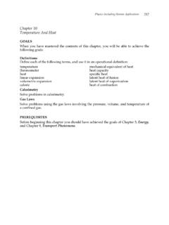
1 5-9 Chapter 5 The maximum coefficient of performance b for the refrigeration cycle is given by b = CcycleQW = CHCQQQ-= CHCTTT- The maximum coefficient of performance gfor the heat pump cycle is given by g = HcycleQW = HHCQQQ-= HHCTTT- Example ---------------------------------------- ---------------------------------------- -- By steadily circulating a refrigerant at low temperature through passages in the walls of the freezer compartment, a refrigerator maintains the freezer compartment at 5 C when the air surrounding the refrigerator is at 22 C. The rate of heat transfer from the freezer compartment to the refrigerant is 8000 kJ/h and the power input required to operate the refrigerator is 3200 kJ/h. Determine the coefficient of performance of the refrigerator and compare with the coefficient of performance of a reversible refrigeration cycle operating between reservoirs at the same two temperatures.
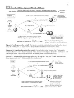
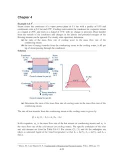
2 Solution ---------------------------------------- ---------------------------------------- ---------- SystemHigh T = 295 KHot reservoirLow T = 268 KCold reservoirQH QC W = 3200 kJ/hcycleRefrigeration cycleQ= 8000 kJ/hc The coefficient of performance b for the refrigeration cycle is given by b = CcycleQW = CcycleQW = 8,000 kJ/h3,200 kJ/h = The maximum coefficient of performance b for the refrigeration cycle is given by 3 Moran, M. J. and Shapiro H. N., Fundamentals of Engineering Thermodynamics, Wiley, 2008, pg. 236 5-10 b max = CcycleQW = CHCQQQ-= CHCTTT- = 268 K295 K-268 K = Example ---------------------------------------- ---------------------------------------- -- A dwelling requires 6 105 Btu per day to maintain its temperature at 70 F when the outside temperature is 32 F. (a) If an electric heat pump is used to supply this energy, determine the minimum theoretical work input for one day of operation, in Btu/day.
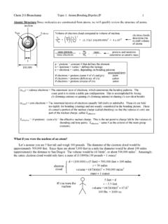
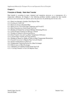
3 (b) Evaluating electricity at 8 cents per kW h, determine the minimum theoretical cost to operate the heat pump, in $/day. Solution ---------------------------------------- ---------------------------------------- ---------- SystemHigh T = 530 RHot reservoirLow T = 492 RCold reservoirQH QC W = ?cycleHeat Pump cycleQ= 6x10 Btu/hH 5 The maximum coefficient of performance g for the heat pump cycle is given by gmax = HcycleQW = HHCQQQ-= HHCTTT- The minimum theoretical work input is then: Wmin = maxHQg= HCHHTTQT- Wmin = HCHHTTQT- = (6 105 Btu/day) ()530 - 492R530 R = 104 Btu/day The minimum cost is Cost = ( 104 Btu/day)1 kWh3413 Btu $kWh = $/day 4 Moran, M. J. and Shapiro H. N., Fundamentals of Engineering Thermodynamics, Wiley, 2008, pg. 238 5-11 Carnot Cycles A Carnot cycle is the most efficient type of cycle we can possibly have. Figure shows an ideal gas in a piston-cylinder assembly undergoing a Carnot cycle.
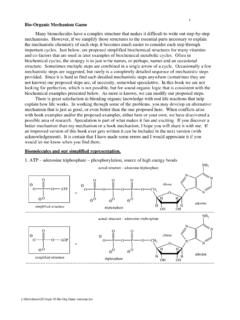
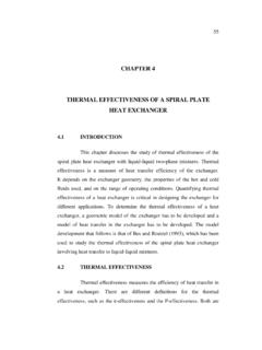
4 In this cycle, the gas goes through four reversible processes through which it returns to its initial state. 2 12 33 41 4 AdiabaticcompressionIsothermalexpansionA diabaticexpansionIsothermalcompressionQH QCC onstant THConstant TC Figure Carnot power cycle for an ideal gas. The four processes of the cycle are Process 1-2: The gas is compress adiabatically to state 2, where the temperature is TH. Process 2 3: The gas expands isothermally while receiving energy QH from the hot reservoir at TH by heat transfer. Process 3 4: The gas is allowed to continue to expand adiabatically until the temperature drops to TC. Process 4 1: The gas is compressed isothermally to its initial state while it discharges energy QC to the cold reservoir at TC by heat transfer. The net work obtained in a Carnot cycle is given by the sum of the work obtained in all processes: - Wcycle = 23W + 34W - 41W - 12W 5-12 Figure pv diagram for a Carnot cycle.
5 The sign of Wcycle is negative since the overall effect of the Carnot cycle shown in Figure is to deliver work from the system to the surroundings. The Carnot power cycle can be operated in the opposite direction to act as a refrigeration or heat pump cycle. Example ---------------------------------------- ---------------------------------------- -- Consider 1 mole of an ideal gas in a piston-cylinder assembly. This gas undergoes a power cycle, which is described below. The heat capacity is constant, vc = = ( ) ( J/mol K). 1) A reversible, isothermal expansion from bar to 8 bar. 2) A reversible, adiabatic expansion from 8 bar and 1000 K to 850 K. 3) A reversible, isothermal compression at 850 K. 4) A reversible, adiabatic compression from 850 K to 1000 K and bar. Perform the following analysis: a) Calculate Q, W, and DU for each of the steps in the cycle. b) Draw the cycle on a pv diagram.
6 C) Calculate the efficiency of the cycle and compare with that of the Carnot cycle. Solution ---------------------------------------- ---------------------------------------- ---------- a) Calculate Q, W, and DU for each of the steps in the cycle. 5 Koretsky , Engineering and Chemical Thermodynamics, Wiley, 2004, pg. 89 5-13 Step 1: A reversible, isothermal expansion at 1000 K bar to 8 bar. DU = 0 for isothermal, ideal gas W = - 8 barpdV Since V = nRTp dV = - 2nRTpdp W = 8 barnRTdpp = - nRT ln( ) W = - (1 mol)( J/mol K)(1000 K) ln( ) = - 1,938 J DU = 0 = QH + W QH = - W = 1,938 J V1 = 11nRTp = 5(1 mol)( J/mol K)(1000 K) Pa = m3 Step 2: A reversible, adiabatic expansion from 8 bar and 1000 K to 850 K. Q = 0 for adiabatic process DU = nvc(T3 - T2) = (1 mol)( * J/mol K)(850 - 1000) K = - 1,871 J W = DU = - 1,871 J V2 = 22nRTp = 5(1 mol)( J/mol K)(1000 K) Pa = m3 Step 3: A reversible, isothermal compression at 850 K.
7 DU = 0 for isothermal, ideal gas W = - 43pppdV = 43ppnRTdpp = nRT ln(p4/p3) Since process 2-3 is adiabatic and reversible: p2V2k = p3V3k where k = pvcc = vvcRc+ k = + = 53 = Using ideal gas law 5-14 p2V2k = ()212kknRTp- = 390 = ()313kknRTp- (Note: p2 = 8 bar, V2 = m3) Solving for p3 we get p3 = () = 105 Pa = bar Similarly for p4 we have p1V1k = p4V4k p1V1k = ()111kknRTp- = = ()414kknRTp- (Note: p2 = bar, V1 = m3) Solving for p4 we get p4 = () = 105 Pa = bar W = nRT ln(p4/p3) = (1mol)( J/mol K)(850 K) ln( ) = 1,656 J DU = 0 = QL + W QL = - W = - 1,656 J Step 4: A reversible, adiabatic compression from bar and 850 K to bar and 1000 K. Q = 0 for adiabatic process DU = nvc(T4 - T1) = (1 mol)( * J/mol K)(1000 - 850) K = 1,871 J W = DU = 1,871 J Table Results of the calculation Process DU(J) W(J) Q(J) State 1 to 2 0 - 1,938 1,938 State 2 to 3 - 1,871 - 1,871 0 State 3 to 4 0 1,656 - 1,656 State 4 to 1 1,871 1,871 0 Total 0 - 282 282 5-15 Table T , p, and V for the cycle State T(K) p(bat) V(m3) (1) 1000 (2) 1000 (3) 850 (4) 850 b) Draw the cycle on a pv diagram.
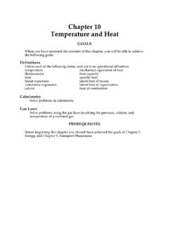
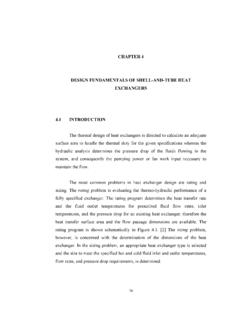
8 The pv diagram can be plotted from the following Matlab program % pv diagram Th=1000;Tc=850;R= ; ph= ;pl=8e5; v1=R*Th/ph; v2=R*Th/pl; % Process 1 to 2 (isothermal expansion) v12=linspace(v1,v2,50); p12=R* ; % Process 2 to 3 (adiabatic expansion) k=5/3;con=(R*Th)^k/pl^(k-1); T=linspace(Th,Tc,50); p23=(((R*T).^k)/con).^ ; v23=R* ;v3=v23(50); % Process 3 to 4 (isothermal compression) con2=(R*Th)^k/ph^(k-1); p4=(((R*Tc)^k)/con2)^ ; v4=R*Tc/p4; v34=linspace(v4,v3); p34=R* ; % Process 4 to 1 (adiabatic compression) p41=(((R*T).^k)/con2).^ ; v41=R* ; plot(v12,p12,v23,p23,v34,p34,v41,p41) grid on ylabel('p(Pa)');xlabel('v(m^3)') 5-16 Figure pv diagram c) Calculate the efficiency of the cycle and compare with that of the Carnot cycle. The thermal efficiency h of the power cycle is given by h = cycleHWQ = 2821938 = The thermal efficiency h of the Carnot power cycle is given by h = cycleHWQ = 1 - CHQQ = 1 - CHTT = 1 - 8501000 = Therefore the given power cycle is a Carnot cycle.
9 The small difference is due to round off error.