Transcription of Chapter 5 - Loop Antennas
1 Loop Antennas 5-1A loop antenna is a closed-circuit antenna that is, one in which a conductor is formed into one or more turns so its two ends are close together. Loops can be divided into two general classes,those in which both the total conductor length and the maximum linear dimension of a turn arevery small compared with the wavelength, and those in which both the conductor length and the loopdimensions begin to be comparable with the small loop can be considered to be simply a rather large coil, and the current distribution insuch a loop is the same as in a coil. That is, the current has the same phase and the same amplitude inevery part of the loop. To meet this condition, the total length of conductor in the loop must not exceedabout . Small loops are discussed later in this Chapter , and further in Chapter large loop is one in which the current is not the same either in amplitude or phase in every partof the loop.
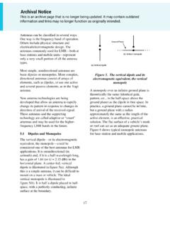
2 This change in current distribution gives rise to entirely different properties as comparedwith a small LoopsThe smallest size of large loop generally used is one having a conductor length of 1/2 . The conductoris usually formed into a square, as shown in Fig 1, making each side 1/8 long. When fed at the center of oneside, the current flows in a closed loop as shown at A. The current distribution is approximately the same ason a 1/2- wire, and so is maximum at the center of the side opposite the terminals X-Y, and minimum at theterminals themselves. This current distribution causes the field strength to be maximum in the plane of theloop and in the direction looking from the low-current side to the high-current side. If the side opposite theterminals is opened at the center as shown at B (strictly speaking, it is then no longer a loop because it is nolonger a closed circuit), the direction of current flow remains unchanged but the maximum current flowoccurs at the terminals.
3 This reverses the direction of maximum radiation resistance at a current antinode (which is also the resistance at X-Y in Fig 1B) is onthe order of 50 . The impedance at the terminals in A is a few thousand ohms. This can be reduced byusing two identical loops side by side with a few inches spacing between them and applying powerbetween terminal X on one loop and terminal Y on the a 1/2- dipole or a small loop, there is no direction in which the radiation from a loop of the typeshown in Fig 1 is zero. There is appreciable radiation in the direction perpendicular to the plane of the loop,as well as to the rear the opposite direction tothe arrows shown. The front-to-back (F/B) ratio isof the order of 4 to 6 dB. The small size and theshape of the directive pattern result in a loss of about1 dB when the field strength in the optimum direc-tion from such a loop is compared with the fieldfrom a 1/2- dipole in its optimum ratio of the forward radiation to the back-ward radiation can be increased, and the fieldstrength likewise increased at the same time to givea gain of about 1 dB over a dipole, by using induc-tive reactances to load the sides joining the frontChapter 5 Loop AntennasFig 1 Half-wave loops, consisting of a singleturn having a total length of 1/2.
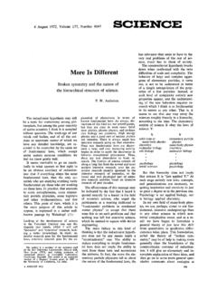
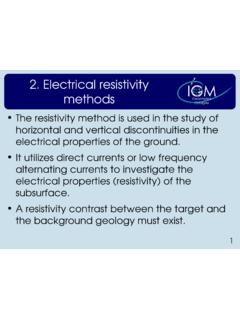
4 5-2 Chapter 5and back of the loop. This is shown in Fig 2. The reactances, which should have a value of approximately360 , decrease the current in the sides in which they are inserted and increase it in the side having termi-nals. This increases the directivity and thus increases the efficiency of the loop as a LoopsLoops in which the conductor length is 1 have different characteristics than 1/2- loops. Three forms of1- loops are shown in Fig 3. At A and B the sides of the squares are equal to 1/4 , the difference being in thepoint at which the terminals are inserted. At C the sides of the triangle are equal to 1/3 . The relativedirection of current flow is as shown in the drawings. This direction reverses halfway around the perimeterof the loop, as such reversals always occur at the junction of each 1/2- section of directional characteristics of loops of this type are opposite in sense to those of a small loop.
5 Thatis, the radiation is maximum perpendicular to the plane of the loop and is minimum in any direction in theplane containing the loop. If the three loops shown in Fig 3 are mounted in a vertical plane with the terminalsat the bottom, the radiation is horizontally polarized. When the terminals are moved to the center of onevertical side in A, or to a side corner in B, the radiation is vertically polarized. If the terminals are moved toa side corner in C, the polarization will be diagonal, containing both vertical and horizontal contrast to straight-wire Antennas , the electrical length of the circumference of a 1- loop is shorterthan the actual length. For loops made of wire and operating at frequencies below 30 MHz or so, where theratio of conductor length to wire diameter is large, the loop will be close to resonance whenLength1005ffeetMHz=The radiation resistance of a resonant 1- loop is approximately 100 , when the ratio of conductorlength to diameter is large.
6 As the loop dimensions are comparable with those of a 1/2- dipole, the radiationefficiency is the direction of maximum radiation (that is, broadside to the plane of the loop, regardless of thepoint at which it is fed) the 1- loop will show a small gain over a 1/2- dipole. Theoretically, this gainis about 2 dB, and measurements have confirmed that it is of this 1- loop is more frequently used as an element of a directive antenna array (the quad anddelta-loop Antennas described in Chapter 12) than singly, although there is no reason why it cannot beused alone. In the quad and delta loop, it is nearly always driven so that the polarization is Loop AntennasThe electrically small loop antenna has existed in various forms for many years. Probably the mostfamiliar form of this antenna is the ferrite loopstick found in portable AM broadcast-band applications of the small loop include direction finding, low-noise directional receiving an-Fig 3 At A and B, loops having sides 1/4 long,and at C having sides 1/3 long (total conductorlength 1 ).
7 The polarization depends on theorientation of the loop and on the position of thefeed point (terminals X-Y) around the perimeter ofthe 2 Inductive loading in the sides of a 1/2- loop to increase the directivity and radiation or response is in the plane ofthe loop, in the direction shown by the Antennas 5-3tennas for and MHz, and small transmitting Antennas . Because the design of transmitting andreceiving loops requires some different considerations, the two situations are examined separately inthis section. This information was written by Domenic M. Mallozzi, Basic LoopWhat is, and what is not a small loop antenna? By definition, the loop is considered to be electri-cally small when its total conductor length is less than is the number used in this size is based on the fact that the current around the perimeter of the loop must be in phase.
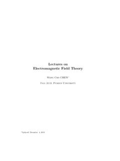
8 Whenthe winding conductor is more than about , this is no longer true. This constraint results in avery predictable figure-eight radiation pattern, shown in Fig simplest loop is a 1-turn untuned loop with a load connected to a pair of terminals located inthe center of one of the sides, Fig 5. How its pattern is developed is easily pictured if we look at some snapshots of the antenna relative to a signal source. Fig 6 represents a loop from above, and shows theinstantaneous radiated voltage wave. Note that points A and B of the loop are receiving the same instanta-neous voltage. This means that no current will flow through the loop, because there is no current flowbetween points of equal potential. A similar analysis of Fig 7, with the loop turned 90 from the positionrepresented in Fig 6, shows that this position of the loop provides maximum response.
9 Of course, the voltagederived from the passing wave is small because of the small physical size of the loop. Fig 4 shows the idealradiation pattern for a small voltage across the loop terminals is givenbyV2 ANEcos= (Eq 1)whereV = voltage across the loop terminalsA = area of loop in square metersN = number of turns in the loopE = RF field strength in volts per meter = angle between the plane of the loop and the signal source (transmitting station) = wavelength of operation in metersThis equation comes from a term called ef-Fig 4 Calculated small loop antenna 5 Simpleuntuned smallloop 6 Example of orientation of loop antennathat does not respond to a signal source (null inpattern).5-4 Chapter 5height (length) of a vertical piece of wire aboveground that would deliver the same voltage tothe receiver. The equation for effective heightish2NA= (Eq 2)where h is in meters and the other terms are asfor Eq few minutes with a calculator will showthat, with the constraints previously stated, theloop antenna will have a very small effectiveheight.
10 This means it will deliver a relativelysmall voltage to the receiver, with even a LOOPSWe can tune the loop by placing a capacitor across the antenna terminals. This causes a largervoltage to appear across the loop terminals because of the Q of the parallel resonant circuit that voltage across the loop terminals is now given byV2 ANEQcos= (Eq 3)where Q is the loaded Q of the tuned circuit, and other terms are as defined amateur loops are of the tuned variety. For this reason, all comments that follow are based ontuned-loop Antennas , consisting of one or more turns. The tuned-loop antenna has some particularadvantages. For example, it puts high selectivity up at the front of a receiving system, where it cansignificantly help factors such as dynamic range. Loaded Q values of 100 or greater are easy to obtainwith careful loop a situation where the inherent selectivity of the loop is helpful.