Transcription of Chapter 5 Transient Analysis - CAU
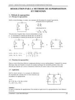
1 Chapter 5. Transient Analysis Jaesung Jang Complete response = Transient response + Steady-state response Time Constant First order and Second order Differential Equation . 1. Transient Analysis The difference of Analysis of circuits with energy storage elements (inductors or capacitors) & time-varying signals with resistive circuits is that the equations resulting from KVL and KCL are now differential equations rather than algebraic linear equations resulting from the resistive circuits. Transient region: the region where the signals are highly dependent on time. (temporary). No voltage or current sources Transient Analysis 1. 0. 9. Steady-state region: the region where the 0. 8. signals are not time dependent (time rate of 0. 7. 0. 6. change of signals is equal to zero) or V/Vs 0. 5. periodic. d( ). 0. 4. =0 0. 3. Constant signals dt 0. 2. 0. 1. Sinusoidal signals 0. 0 1 2 3 4 5.
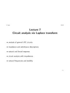
2 T (s e c ). 6 7 8 9 10. 2. Solution of Ordinary Differential Equation Transient solution (xN) is a solution of the dx homogeneous equation: Transient (natural) + x = Vs response. -> temporary behavior without the dt source. Steady-state (particular) solution (xF) is a solution dx N. due to the source: steady-state (forced ) + xN = 0. dt response. Complete response = Transient (natural) response dx F. + x F = Vs + steady-state (forced ) response -> x = xN + xF dt First order: The largest order of the differential 1. equation is the first order. RL or RC circuit. Second order: The largest order of the differential V/Vs equation is the second order. RLC or LC circuit. 0. 0 1 2 3 4 5 6 7 8 9 10. t (s ec ). 3. Writing Differential Equations Key laws: KVL & KCL for capacitor voltages or inductor currents vR. KCL : iR = iC = iC. R. KVL : v S + v R + vC = 0 v S + iR R + vC = 0. iC (t ).
3 T iC R + vC (t = 0) + dt = v S. C. 0. diC i dv di i dv R + C = S C + C = S : Differential equation for iC. dt C dt dt RC Rdt vR dv v vC dv v v = iC = C C = S C + C = S : Differential equation for vC. R dt R dt RC RC. dx(t ). a1 + a0 x(t ) = b0 f (t ). dt where x(t ) represents the capacitor voltage or the inductor current and the constants a1 , a0 , and b0 represents combinations of circuit element parameters. First - order linear ordinary differential equation 4. Writing Differential Equations (cont.). KCL : iR = iC = iL = i Key laws: KVL & KCL. KVL : v S + v R + vC + v L = 0 vS + iR R + vC + v L = 0. i(t ). t iR + vC (t = 0 ) +. di 0. C. dt + L = v S. dt 2. di i d i dvS d 2i Rdi i dv R+ +L 2 = 2+ + = S : Differential equation for i dt C dt dt dt Ldt LC Ldt vR dv v vC v L dv v v 1 d dv . = iC = C C = S C C = S C L C C . R dt R dt R R R dt dt . dvC d 2 vC . RC = v S vC LC 2 . dt dt.
4 D 2 vC . LC + RC dvC + vC = vS : Differential equation for vC. dt 2 dt . d x(t ). 2. dx(t ). a2 + a1 + a0 x(t ) = b0 f (t ) Second - order linear ordinary differential equation dt 2 dt where x(t ) represents the capacitor voltage or the current and the constants a 2 , a1 , a0 , and b0 represents combinations of circuit element parameters. a2 d 2 x(t ) a1 dx(t ) 1 d 2 x(t ) 2 dx(t ). + x(t ) = f (t ) 2 + x(t ) = K S f (t ). b0. + +. a0 dt 2 a0 dt a0 n dt 2 n dt where the constants n = a0 a 2 , = (a1 2) 1 a0 a2 and K S = b0 a0 termed the natural frequency, the damping ratio, 5. and the DC gain, respectively. Examples of Writing Differential Equations vR. KCL : i R1 = iL + i R2 = iL + i R2. R. KVL : v S + v R + v L = 0 v R = vS v L. v (t ). t v vL. = iL (t = 0) + L. vR v R. = i L + i R2 S. R L . dt + L. 0. R. Rv L (t ) Rv L (t ). t t v S v L = RiL (t = 0 ) + dt + v L v S = RiL (t = 0 ) + dt + 2v L.
5 L L. 0 0. dvS R 2dvL dv R dv = vL + 2 L + v L = S : Differential equation for v L. dt L dt dt L dt KCL : iR1 = iC + i L. KVL : vS + v R1 + vC = 0 vS = v R1 + vC. diL. vC + v R2 + v L = 0 vC = v R2 + v L = L + iL R2. dt dvC d diL d 2 iL . v R1 = i R1 R1 = (iC + iL )R1 = C. di + iL R1 = C L + iL R2 + i L R1 = LC 2 + R2C L + i L R1.. dt dt dt dt dt . d 2. i di di v S = v R1 + vC = LC 2L + R2 C L + iL R1 + L L + i L R2 . dt dt dt . d 2i L diL di v S = R1 LC + R1 R2C + R1i L + L L + iL R2 . dt 2 dt dt d 2 iL. + (R1 R2 C + L ) + (R1 + R2 )iL = vS : Differential equation for iL. diL. R1 LC 6. dt 2 dt DC steady state solution: Final Condition Steady state solution due to AC (sinusoidal waveforms) is in Chap. 6 (frequency response). DC steady state solution: response of a circuit that have been connected to a DC. source for a long time or response of a circuit long after a switch has been activated.
6 All the time derivatives are equal to zero at the steady state. Capacitors: insulators (very large resistances) are inside the capacitors. Inductors: Induction works only when the change in electric fields happens. dvC (t ). iC (t ) = C 0 as t . + dt di (t ). +. + v L (t ) = L L 0 as t . + dt At DC steady state, all capacitors behave as open circuits and all inductors hehave as short circuits. d 2 iL. + (R1 R2C + L ) + (R1 + R2 )iL = vS. dvC vC v di L. + = S R1 LC 2. dt RC RC dt dt vC = v S at the steady state vS. iL = at the steady state 7. (R1 + R2 ). DC steady state solution: Initial Condition Initial condition: response of a circuit before a switch is first activated. Since power equals energy per unit time, finite power requires continuous change in energy. Primary variables: capacitor voltages and inductor currents-> energy WL (t ) = Li L2 (t ) WC (t ) = CvC2 (t ). 1 1. storage elements 2 2.
7 Capacitor voltages and inductor currents cannot change instantaneously but should be continuous. -> continuity of capacitor voltages and inductor currents The value of an inductor current or a capacitor voltage just prior to the closing (or opening) of a switch is equal to the value just after the switch has been closed (or opened). ( ) ( ). vC t = 0 = vC t = 0 +. iL (t = 0 ) = i (t = 0 ).. L. +. where the notation 0 signifies " just before t = 0" and 0 + signifies " just after t = 0" Discontinuous of capacitor voltage -> infinite power at t=0. 8. First Order Response First-order circuit: one energy storage element + one energy loss element ( RC circuit, RL circuit). Procedures Write the differential equation of the circuit for t=0+, that is, immediately after the switch has changed. The variable x(t) in the differential equation will be either a capacitor voltage or an inductor current.
8 You can reduce the circuit to thevenin or Norton equivalent form. Identify the initial conditions x(t=0+) [= x(t=0-)] and final conditions x(t= ). Solve the differential equation. Write the complete solution for the circuit in the form. x(t ) = x(t = ) + [x(t = 0 ) x(t = )]exp( t ). The time constant ( ) is a measure of how fast capacitor voltages or inductor currents react to the input (voltage or current source). It is a period of time during which capacitor voltages or inductor currents change by to get to the steady state. [x(t = ) x(t = 0)]. = 1 e 1 = [x(t = ) x(t = 0)]. 9. First Order Response (cont.). First-order circuit: one energy storage element + one energy loss element ( RC circuit, RL circuit). dx (t ) a dx (t ) dx(t ). + a0 x (t ) = b0 f (t ) 1 + x(t ) = 0 f (t ) + x (t ) = K S f (t ). b a1. dt a0 dt a0 dt where = a1 a0 and K S = b0 a0 termed the time constant and DC gain, respectively.
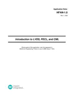
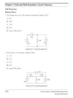
9 Natural Response dx (t ) dx (t ) x N (t ). N + x N (t ) = 0 N = x N (t ) = x0 e t where x0 is a constant. dt dt . dx (t ). Forced Response due to DC (where f (t ) = F ) : F 0. dt dx (t ). F + x F (t ) = K S F t 0 x F (t ) = K S F t 0. dt Complete Response x(t ) = x N (t ) + x F (t ) = x0 e t + x(t = ) = x0 e t + K S F (for DC). x(t = 0 ) = x0 + x(t = ) x0 = x(t = 0 ) x(t = ) for t 0 10. Example: First Order Response 1. +. vR. Step1 : KCL : iR = iC = iC. R. KVL : v S + v R + vC = 0 v S + i R R + vC = 0. v vC dx(t ). + x(t ) = K S F. vR dv dv = iC = C C = S RC C + vC = v S t > 0 . R dt R dt dt ( ) ( ). Step2 : vC t = 0 = 5 V = vC t = 0 + , vC (t = ) = 12V(= v S ). Step3 : x = vC , = RC = 1k 470 F = , K S = 1, F = vS. Step4 : vC (t ) = (vC (t = 0) vC (t = ))e t + vC (t = ) = 12 + ( 7 )e t 11. Example: First Order Response 2. Step1 : KCL : iR = i L. di L. KVL : v B + v R + v L = 0 v B + i L R + L =0.
10 + dt dx(t ). + x(t ) = K S F. L di L v + iL = B t > 0 . R dt R dt ( ) ( ). Step2 : iL t = 0 = 0 A = iL t = 0 + , iL (t = ) = v B R = Step3 : x = i L , = L R = 4 = , K S = 1 R , F = v B. Step4 : iL (t ) = (i L (t = 0) i L (t = ))e t + i L (t = ) = + ( )e t 12. First Order Transient Response Using thevenin /Norton Theorem One must be careful to determine the equivalent circuits before and after the switch changes position. it is possible that equivalent circuit seen by the load before activating the switch is different from the circuit seen after closing the switch. vC (t ) = V2 t 0 ( ) (. vC t = 0 = V2 = vC t = 0 + ). 13. First Order Transient Response Using thevenin /Norton Theorem (cont.). Page 11. dx(t ) dx(t ). + x(t ) = K S F. dvC. dv Step1 : RT C C + vC = VT t > 0 + x(t ) = K S F Step1 : RC + vC = v S t > 0 . dt dt ( ) ( ). dt dt ( ) ( ). Step2 : vC t = 0 = V2 = vC t = 0 + , vC (t = ) = VT Step2 : vC t = 0 = vC t = 0 + , vC (t = ) = v S.