Transcription of CHAPTER 6 – CMOS OPERATIONAL AMPLIFIERS
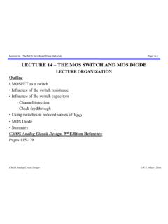
1 CHAPTER 6 Introduction (8/3/05) Page cmos Analog Circuit Design Allen - 2005 CHAPTER 6 cmos OPERATIONAL AMPLIFIERS CHAPTER Outline Design of cmos Op Amps Compensation of Op Amps Two-Stage OPERATIONAL amplifier Design Power Supply Rejection Ratio of the Two-Stage Op Amp Cascode Op Amps Simulation and Measurement of Op Amps Macromodels for Op Amps Summary Goal Understand the analysis, design, and measurement of simple cmos op amps Design Hierarchy The op amps of this CHAPTER are unbuffered and are OTAs but we will use the generic term op amp . Blocks or circuits(Combination of primitives, independent)Sub-blocks or subcircuits(A primitive, not independent)Functional blocks or circuits(Perform a complex function)Fig. 6 CHAPTER 6 Section 1 (8/3/05) Page cmos Analog Circuit Design Allen - 2005 SECTION - DESIGN OF cmos OPERATIONAL AMPLIFIERS High-Level Viewpoint of an Op Amp Block diagram of a general, two-stage op amp: Differential TransconductanceStageHighGainStageOutput BufferCompensationCircuitryBiasCircuitry +-v1vOUTv2vOUT'Fig.
2 110-01 Differential transconductance stage: Forms the input and sometimes provides the differential-to-single ended conversion. High gain stage: Provides the voltage gain required by the op amp together with the input stage. Output buffer: Used if the op amp must drive a low resistance. Compensation: Necessary to keep the op amp stable when resistive negative feedback is applied. CHAPTER 6 Section 1 (8/3/05) Page cmos Analog Circuit Design Allen - 2005 Ideal Op Amp Symbol: +-+-+-v1v2vOUT = Av(v1-v2)VDDVSSFig. 110-02+-i1i2+-vi Null port: If the differential gain of the op amp is large enough then input terminal pair becomes a null port. A null port is a pair of terminals where the voltage is zero and the current is zero. , v1 - v2 = vi = 0 and i1 = 0 and i2 = 0 Therefore, ideal op amps can be analyzed by assuming the differential input voltage is zero and that no current flows into or out of the differential inputs.
3 CHAPTER 6 Section 1 (8/3/05) Page cmos Analog Circuit Design Allen - 2005 General Configuration of the Op Amp as a Voltage amplifier +-+-+-+-v1v2voutFig. 110-03vinpvinnR1R2 Noniverting voltage amplifier : vinn = 0 vout = R1+R2R1vinp Inverting voltage amplifier : vinp = 0 vout = - R2R1 vinn CHAPTER 6 Section 1 (8/3/05) Page cmos Analog Circuit Design Allen - 2005 Example - Simplified Analysis of an Op Amp Circuit The circuit shown below is an inverting voltage amplifier using an op amp. Find the voltage transfer function, vout/vin. +-+-+-+-vinvivoutR2R1iii1i2 Virtual GroundFig. 110-04 Solution If Av , then vi 0 because of the negative feedback path through R2. (The op amp with fb. makes its input terminal voltages equal.) vi = 0 and ii = 0 Note that the null port becomes the familiar virtual ground if one of the op amp input terminals is on ground.
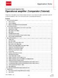
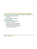
4 If this is the case, then we can write that i1 = vinR1 and i2 = voutR2 Since, ii = 0, then i1 + i2 = 0 giving the desired result as voutvin = - R2R1 . CHAPTER 6 Section 1 (8/3/05) Page cmos Analog Circuit Design Allen - 2005 Linear and Static Characterization of the Op Amp A model for a nonideal op amp that includes some of the linear, static nonidealities: +-v2v1v1 CMRRVOSRicmRicmin2en2IB1IB2 CidRidRoutvoutIdeal Op AmpFig. 110-05* where Rid = differential input resistance Cid = differential input capacitance Ricm = common mode input resistance VOS = input-offset voltage IB1 and IB2 = differential input-bias currents IOS = input-offset current (IOS = IB1-IB2) CMRR = common-mode rejection ratio e2n = voltage-noise spectral density (mean-square volts/Hertz) i2n = current-noise spectral density (mean-square amps/Hertz) CHAPTER 6 Section 1 (8/3/05) Page cmos Analog Circuit Design Allen - 2005 Linear and Dynamic Characteristics of the Op Amp Differential and common-mode frequency response: Vout(s) = Av(s)[V1(s) - V2(s)] Ac(s) V1(s)+V2(s)2 Differential-frequency response: Av(s) = Av0 sp1 - 1 sp2 - 1 sp3 - 1 = Av0 p1p2p3 (s -p1)(s -p2)(s -p3) where p1, p2, p3, are the poles of the differential-frequency response (ignoring zeros).
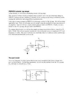
5 0dB20log10(Av0)|Av(j )| dBAsymptoticMagnitudeActualMagnitude 1 2 3 -6 110-06 CHAPTER 6 Section 1 (8/3/05) Page cmos Analog Circuit Design Allen - 2005 Other Characteristics of the Op Amp Power supply rejection ratio (PSRR): PSRR = VDD VOUT Av(s) = Vo/Vin (Vdd = 0)Vo/Vdd (Vin = 0) Input common mode range (ICMR): ICMR = the voltage range over which the input common-mode signal can vary without influence the differential performance Slew rate (SR): SR = output voltage rate limit of the op amp Settling time (Ts): +-Settling TimeFinal ValueFinal Value + Final Value - vOUT(t)t00vOUTvINFig. 110-07 TsUpper ToleranceLower Tolerance CHAPTER 6 Section 1 (8/3/05) Page cmos Analog Circuit Design Allen - 2005 Classification of cmos Op Amps Categorization of op amps: ConversionClassic DifferentialAmplifierModified DifferentialAmplifierDifferential-to-sin gle endedLoad (Current Mirror)Source/SinkCurrent LoadsMOS DiodeLoadTransconductanceGrounded GateTransconductanceGrounded SourceClass A (Sourceor Sink Load)Class B(Push-Pull)Voltageto CurrentCurrentto VoltageVoltageto CurrentCurrentto VoltageHierarchyFirstVoltageStageSecondV oltageStageCurrentStageTable 110-01 CHAPTER 6 Section 1 (8/3/05) Page cmos Analog Circuit Design Allen - 2005 Two-Stage cmos Op Amp Classical two-stage cmos op amp broken into voltage-to-current and current-to-voltage stages: +--+vinM1 M2M3 M4M5M6M7voutVDDVSSV II VV II VvoutvinVBiasFig.
6 CHAPTER 6 Section 1 (8/3/05) Page cmos Analog Circuit Design Allen - 2005 Folded Cascode cmos Op Amp Folded cascode cmos op amp broken into stages. VSSVDDM1M2M6M4M3M5M7M8M10M9M11 VBiasVBiasVBias+-vinvout+-V II II VvoutvinFig. CHAPTER 6 Section 1 (8/3/05) Page cmos Analog Circuit Design Allen - 2005 Design of cmos Op Amps Steps: 1.) Choosing or creating the basic structure of the op amp. This step is results in a schematic showing the transistors and their interconnections. This diagram does not change throughout the remainder of the design unless the specifications cannot be met, then a new or modified structure must be developed. 2.) Selection of the dc currents and transistor sizes. Most of the effort of design is in this category. Simulators are used to aid the designer in this phase. The general performance of the circuit should be known a priori.
7 3.) Physical implementation of the design. Layout of the transistors Floorplanning the connections, pin-outs, power supply buses and grounds Extraction of the physical parasitics and resimulation Verification that the layout is a physical representation of the circuit. 4.) Fabrication 5.) Measurement Verification of the specifications Modification of the design as necessary CHAPTER 6 Section 1 (8/3/05) Page cmos Analog Circuit Design Allen - 2005 Boundary Conditions and Requirements for cmos Op Amps Boundary conditions: 1. Process specification (VT, K', Cox, etc.) 2. Supply voltage and range 3. Supply current and range 4. Operating temperature and range Requirements: 1. Gain 2. Gain bandwidth 3. Settling time 4. Slew rate 5. Common-mode input range, ICMR 6. Common-mode rejection ratio, CMRR 7. Power-supply rejection ratio, PSRR 8.
8 Output-voltage swing 9. Output resistance 10. Offset 11. Noise 12. Layout area CHAPTER 6 Section 1 (8/3/05) Page cmos Analog Circuit Design Allen - 2005 Specifications for a Typical Unbuffered cmos Op Amp Boundary Conditions Requirement Process Specification See Tables and Supply Voltage V 10% Supply Current 100 A Temperature Range 0 to 70 C Specifications Value Gain 70 dB Gainbandwidth 5 MHz Settling Time 1 sec Slew Rate 5 V/ sec Input CMR V CMRR 60 dB PSRR 60 dB Output Swing V Output Resistance N/A, capacitive load only Offset 10 mV Noise 100nV/Hz at 1 KHz Layout Area 10,000 min. channel length2 CHAPTER 6 Section 1 (8/3/05) Page cmos Analog Circuit Design Allen - 2005 Some Practical Thoughts on Op Amp Design 1.) Decide upon a suitable topology.
9 Experience is a great help The topology should be the one capable of meeting most of the specifications Try to avoid inventing a new topology but start with an existing topology 2.) Determine the type of compensation needed to meet the specifications. Consider the load and stability requirements Use some form of Miller compensation or a self-compensated approach (shown later) 3.) Design dc currents and device sizes for proper dc, ac, and transient performance. This begins with hand calculations based upon approximate design equations. Compensation components are also sized in this step of the procedure. After each device is sized by hand, a circuit simulator is used to fine tune the design Two basic steps of design: 1.) First-cut - this step is to use hand calculations to propose a design that has potential of satisfying the specifications.
10 Design robustness is developed in this step. 2.) Optimization - this step uses the computer to refine and optimize the design. CHAPTER 6 Section 2 (8/3/05) Page cmos Analog Circuit Design Allen - 2005 SECTION - COMPENSATION OF OP AMPS Compensation Objective Objective of compensation is to achieve stable operation when negative feedback is applied around the op amp. Types of Compensation 1. Miller - Use of a capacitor feeding back around a high-gain, inverting stage. Miller capacitor only Miller capacitor with an unity-gain buffer to block the forward path through the compensation capacitor. Can eliminate the RHP zero. Miller with a nulling resistor. Similar to Miller but with an added series resistance to gain control over the RHP zero. 2. Self compensating - Load capacitor compensates the op amp (later). 3. Feedforward - Bypassing a positive gain amplifier resulting in phase lead.