Transcription of Chapter 7
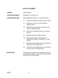
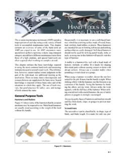
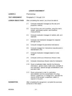
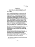
1 Chapter 7. Cranes Cranes are used to hoist and place loads. They are mounted in one of three ways truck, crawler, or rough-terrain (wheel). The truck and rough- terrain mounts do not provide the stability of the crawler mount. Attaching accessory equipment to the crane 's superstructure and boom allows use of the basic machine for pile driving or as an excavator. BASIC crane UNIT. 7-1. The basic crane unit (Figure 7-1) consists of a substructure mount and a full revolving superstructure. The upper revolving superstructure is substantially the same without regard to the substructure mount. Installing attachments allows use of the machine for tasks other than hoisting. Figure 7- 2, page 7-2, shows several crane attachments hook block, clamshell, pile driver, and dragline. Revolving superstructure Truck mounting Crawler mounting Rough-terrain mounting Figure 7-1. Basic crane Unit Cranes 7-1. FM 5-434.
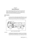
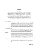
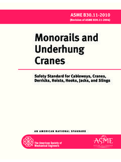
2 Hook block Clamshe ll Dragline Pile driver Figure 7-2. crane Attachments SUBSTRUCTURE. 7-2. The substructure can be a truck, a crawler, or a rough-terrain mount. Each mount has different stabilization and terrain capabilities. Truck Mount 7-3. Truck cranes have specially-designed heavy-duty truck mounts. This mounting provides good between-project mobility. The 20- and 25-ton truck cranes can operate a hook block, a clamshell, a 7,000-foot- pounds-per-blow diesel pile driver, or a dragline. Figure 7-3 shows a 25-ton truck crane with a hydraulic telescopic boom. Stability. These cranes have outriggers on each side. Always employ the outriggers when operating the crane or attachments. Fully extend the outriggers and secure the jacks on the base plates so that the crane is completely off of the tires. Some models are equipped with hydraulic outriggers. Terrain capability. Because of its limited stability, the truck mount restricts the efficient movement of these cranes to firm, level terrain.
3 7-4. Towing. A pintle hook (towing connection) is on the rear of the truck, and towing eyes are on the front. The pintle hook enables the truck to tow an attachment trailer for transporting associated attachments to the job site. If the truck becomes inoperable or stuck, use the towing eyes to attach the truck to a towing vehicle. The towing eyes will withstand twice the dead-weight pull of the vehicle. 7-2 Cranes FM 5-434. Boom-tip Boom assembly fly Boom section mid- section Boom main section Counterweight Swing-away boom extension Floodlights Left rear outrigger Boom Left front lift outrigger cylinder Figure 7-3. Truck crane (25-ton) With a Hydraulic Telescopic Boom 7-5. Operating Hints. Be sure the crane is level prior to operating. Do not hoist loads over the front. Generally, perform all heavy hoisting over the rear of the truck since the truck's cab and engine provide additional counterweight for the load.
4 When using a load chart, ensure that the capacity reflects the quadrant of the proposed hoist. For example, over the side, over the rear of the mount, or over the front of the mount. Use the outriggers. Check the base plates periodically to ensure that good soil bearing is being maintained. Place the truck's transmission in neutral when operating the superstructure. This prevents possible damage to the gears by any rocking movement of the truck. Crawler Mount 7-6. Move crawler cranes from project to project on transport trucks. Crawler cranes have relatively low travel speeds, and long travel causes excessive track wear. Crawler cranes are best suited for longer duration jobs. The crawler mount provides excellent maneuverability on the job site and has low ground-bearing pressure. The 40-ton crawler crane can operate a hook block, a Cranes 7-3. FM 5-434. 2-cubic-yard clamshell, a 24,000-foot-pounds-per-blow diesel pile driver, or a dragline.
5 The military normally uses the 40-ton crane in quarry operations. Stability. The crawler mounting provides a stable base for operating the revolving superstructure. Because of the width and length of the crawler tracks, the weight of the machine spreads over a large area. Terrain capability. Crawler cranes are designed to operate on level ground. A 3 out-of-level condition can result in a 30 percent loss in hoisting capacity. Crawler cranes' low ground-bearing pressure enables them to travel over soft ground. In locations where the ground is extremely soft or unstable, use timber mats to provide a firm footing (Figure 7-4). When not handling a load, the machine can climb slight grades. Figure 7-4. Timber Mats Supporting a Crawler crane on Soft Material 7-7. Crawler cranes can be lashed on barges to operate over water. They can operate in shallow water as long as the water does not enter the revolving superstructure.
6 Before moving the machine into the water, check the water depth and the under-foot conditions. Thoroughly clean and service the machine after working in salt water. Rough-Terrain Mount 7-8. The two models of rough-terrain cranes are the 22- and the (Type I, general purpose, and Type II, airborne/airmobile). The 22-ton rough-terrain crane can operate a hook block, a clamshell, a 7,000-foot- pounds-per-blow diesel pile driver, or a dragline. The main differences between the rough-terrain crane and the truck crane are the large tires and the high ground clearance, which enables the rough-terrain crane to work in areas inaccessible to the truck crane . 7-9. Rough-Terrain crane (22-Ton). Th e ro ugh te rra in cr an e ha s the capability of long-distance highway travel and good job-site maneuverability. The mount provides four-wheel-drive capability, conventional two-wheel steering, four-wheel steering, and crab steering.
7 The travel speed of the machine is 55 mph on the highway. This crane has dual cabs, a lower cab for 7-4 Cranes FM 5-434. highway travel, and a superstructure cab that has both the drive and the crane controls. A pintle hook on the rear of the mount lets it tow an attachment trailer. However, towing the trailer cross-country is not recommended. Stability. Since the mount is not suspended on springs, the front axle must oscillate. This oscillation prevents the mount from tipping or rolling over if one of the front wheels drops into a hole. Use the outriggers to raise the machine off the ground and to level it before extending the boom. If using outriggers to stabilize the machine, position safety wedges on the front axle to prevent oscillation. The outriggers operate individually, allowing the superstructure to be leveled. Load ratings are based on the assumption that the crane is in a level position for the full 360 of swing.
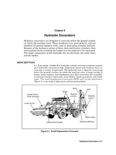
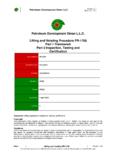
8 Terrain capability. The machine's low ground-bearing pressure lets it travel over relatively soft terrain. It can traverse slopes up to 48. percent if the ground is firm and dry. 7-10. Rough-Terrain crane ( ). The basic 7 .5 -ton rough-terrain crane (Type I) has a diesel engine, pneumatic tires, two- and four-wheel-drive capability, and two- and four-wheel-steering capability. The cab is located on the mount instead of on the full 360 rotating superstructure. It has a hydraulic boom that is extendible from 28 feet to a maximum of 35 feet. This crane can perform lifting and carrying operations (desirable with standard North Atlantic Treaty Organization [NATO] pallets). The rough-terrain, ton airborne crane (Type II) (Figure 7-5) is a modification of the basic unit, making it suitable for airborne and airmobile operations. Stability. The rough-terrain mount has four independently operated outriggers (two on each side).
9 Terrain capability. This crane can safely traverse typical construction terrain, longitudinal grades of 30 to 50 percent, and side slopes of 15 to 30 percent in four-wheel drive. This crane can be used on firm terrain because of its high ground-bearing pressure tires. Figure 7-5. Rough-Terrain, Airborne crane Cranes 7-5. FM 5-434. SUPERSTRUCTURE. 7-11. The revolving superstructure rests on the mount and includes the counterweight, the engine, the operating mechanism, the boom, the cab, and sometimes a separate engine. Counterweight 7-12. The counterweight is normally a cast-steel member attached to the rear of the superstructure to produce a countermoment to the weight and radius of the load. This countermoment prevents the crane from tipping. Operating Mechanisms 7-13. Two independent cable drums control the operation of the various attachments. The drums are mounted parallel to each other or one behind the other.
10 Refer to them by their relative mounting (right or left, front or rear) or by their function (drag cable drum during dragline operations or closing-line cab le drum duri ng cla mshell operations). When using the drums in conjunction with a hook block, refer to them as the rear or main hoist drum. 7-14. A third cable drum, the boom hoist drum, controls the raising and lowering of the boom for those cranes having a lattice boom. Some models have a two-piece, grooved lagging for quick attachment to the drum shaft. The diameters of the grooved lagging differ depending on the make and model of the machine. Differences in lagging diameter provide different operating line speeds. For example, the lagging used for dragline operations may be smaller to provide a slower line that gives greater power. 7-15. Clutches and brakes may be powered mechanically, hydraulically, or pneumatically. Some makes and models have an internally mounted clutch that, when actuated, expands to engage the drum.