Transcription of SINGLE-PHASE MOTORS - sweethaven02.com
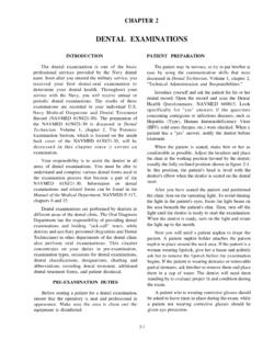
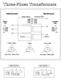
1 FM 55-509-1 CHAPTER 17 SINGLE-PHASE MOTORSINTRODUCTIONS ingle-phase AC MOTORS are the most commonmotors built. Every home, workshop, and vessel hasthem. Since there is such a wide variety of thesemotors, it is impossible to describe all of them. Thischapter will describe the most common types foundon Army 17-1 shows the basicschematic diagrams for the SINGLE-PHASE basic diagram (view A) shows a circle withtwo leads labeled T1 and T2. Just as in the three -phase motor diagram, the motor shows the powersupply lines as being identified with the T. For mostshore facility applications, this is the case. In manycases, the SINGLE-PHASE MOTORS on board a ship will bewired into the lighting distribution panels. The light-ing distribution panels are the source for SINGLE-PHASE power supply. The power distribution panelsare the source of the three -phase power supply. Forthis reason, the SINGLE-PHASE MOTORS are commonlyconnected to L1 and L2, as shown in Figure 17-1shows four SINGLE-PHASE motordiagrams.
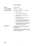
2 Diagram A shows the motor as it will beseen on blueprints and general layouts. It is con-cerned only with the overall operation of theelectrical distribution system. Diagrams B and Cshow a more involved internal wiring system indicat-ing two inductors and three terminals. These diagramsare necessary to understand the exact nature andfunction of the SINGLE-PHASE motor . Refrigerationand manufacturer s wiring schematics also usediagrams B and C to ensure a positive troubleshoot-ing 17-3 shows a very basic one-line diagram of the SINGLE-PHASE motor . Refer back to thisdiagram as the operational requirements of thesingle-phase motor are SINGLE-PHASE induction motor is much thesame in construction as the three -phase SINGLE-PHASE induction MOTORS are also calledsquirrel cage MOTORS because of the rotor s similarityto a circular animal exercise wheel. As discussed inChapter 16, the squirrel cage comprises the bars andshorting-rings that make up the rotor windings.
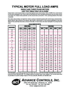
3 Thesquirrel cage is also considered the secondary wind-ings of the motor (Figure 17-4).17-1FM 55-509-1 INDUCTION MOTORSD espite the fact that the three -phase motor hasmore phases than the SINGLE-PHASE motor , the SINGLE-PHASE motor is a much more complex additional components are necessary tooperate the SINGLE-PHASE MOTORS have only two powersource supply lines connected. The single -phasemotor can operate off either the A-B, B-C, C-A,A-N, B-N, or C-N power source phases . The two-wire power supply can provide only a single -phasealternating source (Figure 17-5). The individualsingle-phase current arriving in the stator windingof the SINGLE-PHASE motor does not have the same revolving effect that the three individual phasesof the three -phase power supply provides. Themagnetic field developed by the SINGLE-PHASE cur-rent is created in the stator windings and then isgone. An entire cycle must be completed beforecurrent is again available at the SINGLE-PHASE motorstat prevents the development of therevolving field so easily obtained with the three -phase power supply.
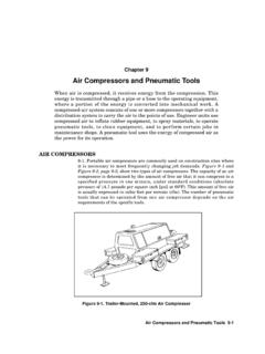
4 The problem with the SINGLE-PHASE motor is its inability to develop a revolving fieldof its own accord. Without a revolving field, torquecannot be developed, and the rotor will never only one stator winding, the SINGLE-PHASE motorcan only produce an oscillating magnetic 55-509-1 Figure 17-6 shows a main winding separatedinto two coils. Each winding is wound in a differentdirection. The importance of the two different coilwinding directions is to emphasize the application ofthe left-hand rule for coils as expressed in previouschapters. By winding the wire in a different direc-tion, the polarity of the coil face closest to the rotorcan be changed. By using one wire wrapped in twodifferent directions, the polarity of every other coilcan be current flows in the main winding, themagnetic field is established throughout the wind-ings (Figure 17-6). Soon the current flow stops andchanges direction (Figure 17-7). With this change incurrent direction comes a change in all the magnetic field of the rotor is developedthrough induction in the same manner as describedfor the three -phase induction motor rotor.
5 Therotor bars and the shorting rings have an inducedEMF created in them, and a current flow current flow establishes a magnetic field ofan opposite polarity of the stator coil directlyacross from it. Unfortunately, there are no over-lapping 120-degree individual stator windings inthis SINGLE-PHASE current changes direction and a newmagnetic field is established in the stator, the inducedrotor magnetic field changes to the opposite polarityof the stator coil directly across from it. All the rotorcan do is oscillate. Without some force to twist orturn the rotor, no torque can be person examining this motor will hear a dis-tinct hum. This is called an AC hum. It is often heardcoming from transformers or SINGLE-PHASE motorsthat are not turning. If the soldier physically turnedthe rotor shaft (not recommended) in either direc-tion, the rotor would start to move. The speed wouldcontinue to increase until it reached its normaloperating : Although certain MOTORS , suchas fans, can be found to be startedphysically by turning the rotor shaft,this action is not a motor does not start ofits own accord, it is because somethingis wrong.
6 If the motor has an electri-cal malfunction, it is not wise to touchthe electrical components when currentis 55-509-lAs long as the rotor s magnetic field is slightlydisplaced from the magnetic field in the stator, atorque can be developed. Slip will keep the rotor sfield slightly behind the stator s field. The differencein speed (relative motion) is necessary to maintainthe torque. Relative motion is necessary to inducethe EMF into the rotor to maintain the rotor s mag-netic field. If the soldier disconnects power andallows the rotor to stop, he again must provide theinitial movement to start the rotor. This is not anacceptable condition for a the use of a three -phase alternatingcurrent, an artificial phase displacement must beestablished. If the stator could only develop anothercurrent, slightly out of phase from the original cur-rent, a revolving field could be assimilated. This isthe problem encountered by SINGLE-PHASE inductionmotors.
7 It is also the area of greatest componentfailure and maintenance requirements, In fact, thespecific names for induction MOTORS represent themeans in which the revolving field is developed froma SINGLE-PHASE power are a multitude of SINGLE-PHASE motorcombinations. This text will discuss only five basicdesigns:Split-phase (resistance-start). motor StartingIn addition to the run or main winding, allinduction SINGLE-PHASE MOTORS are equipped with anauxiliary or start winding in the stator. The auxiliaryor start winding overlaps the main or run provides the revolving field necessary to turn therotor. The terms are used in sets. The frost group isthe run and start set. The second group is the mainand auxiliary winding set. Each group has a commonterminal and Start Winding Set. The term runwinding is used to designate a winding that receivescurrent all the time the motor is in operation. It is theoutermost winding, located next to the motor hous-ing.
8 The term run is used only when the otherwinding is a start start winding is in parallel with the runwinding. The start winding receives current onlyduring the initial starting period. Then it becomesdisconnected from the power source. The startwinding is the set of coils located nearest to therotor (Figure 17-8).Main and Auxiliary Winding Set. The term main winding is used to designate a winding thatreceives current all the time the motor is main winding is located next to the motor hous-ing. The term main is used only when the otherwinding is an auxiliary auxiliary winding receives current all thetime the motor is operating. It is always in parallelwith the main winding. The auxiliary coils are locatedclosest to the rotor. By creating a winding with betterinsulating properties and a motor housing with betterheat dissipation qualities, the auxiliary winding canremain in the circuit as long as the main then increases the motor s running Connection.
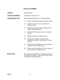
9 The auxiliary or startwinding is connected to the main or run windingthrough a connection called the common. Theauxiliary or start winding is in parallel with the mainor run winding (Figure 17-9). Both the windings in17-4FM 55-509-1the motor use the same SINGLE-PHASE power common connection between the set of windingsis necessary to complete the parallel (RESISTANCE-START)MOTORSF igure 17-10 is a basic one-line diagram of thesplit-phase motor . It shows the run and start windingof the stator as well as the centrifugal switch (CS).The run and start stator windings are con-nected in parallel. If you apply current to bothwindings and establish a magnetic field simul-taneously, the rotor could do nothing more thanoscillate. Unless two or more slightly out of phasecurrents arrive in different windings, torque cannotbe achieved. Every time current changed directions,the magnetic polarities of the stator coils wouldswitch as well.
10 The induced rotor EMF and its result-ing magnetic field would also switch. No torque canbe produced. Something must be done so that a givenmagnetic field in one winding can happen at a slightlydifferent time than in the other winding, thus produc-ing a pulling or pushing effect on the establishedmagnetic polarity in the rotor. The would 17-11 illustrates the run winding(view A) and the start winding (view B) asseparate coils of view C, the two coilsare connected at a common terminal. This ishow the two windings are placed in the circuit 17-12 shows how the start and run wind-ings are in parallel with the same voltage sourceavailable to entering a node must divide betweenthe two windings (Figure 17-13). Magnetism is aproperty of current. Forcing current to arrive at onewinding before it arrives at the other winding wouldcreate the phase difference necessary to create split-phase motor takes advantage of anincreased resistance in the start winding.