Transcription of CHAPTER 7 CONSTRUCTION PROCEDURES - …
1 309 INTRODUCTIONThis CHAPTER presents information of fundamental importance regarding installationand CONSTRUCTION PROCEDURES including base preparation, unloading and assembly,and placement and compaction of the backfill. The emphasis is on corrugated steelpipe in embankment installations such as highway culverts. For pipe in trenchinstallation such as storm sewers, reference should be made to the CSPI publication, Modern Sewer Design for a thorough presentation. For additional information,reference may also be made to ASTM recommended practices under ASTM designations A 796 / A 796 M, A 798 / A 798 M, and A 807 / A 807 well situated, properly bedded, accurately assembled, and carefully backfilledgalvanized steel drainage structure will function properly and efficiently over itsdesign life. Although smaller structures may demand less care in installation thanlarger ones, reasonable precautions in handling, base preparation, assembly andbackfilling are required for all steel structures, because of their strength, light weight and resistanceto fracture, can be installed quickly, easily and with the least expensive flexible steel shell is designed to distribute external loads to the backfill aroundit.
2 Such flexibility permits unequaled tolerance to settlement and dimensionalchanges that would sometimes cause failure in rigid structures. This clear advantageof corrugated steel structures is further strengthened when they are installed on a wellprepared foundation, and surrounded by a well compacted backfill of stable care during installation is required. Just as with drainage structures ofconcrete or other materials, careless installation of corrugated steel structures canundo the work of the CHAPTER 6, minimum cover requirements were presented for corrugated steelpipe under highway and railway loadings. These requirements are based on years ofpractical experience, as well as fundamental design criteria. However, it must beemphasized that such minimum covers may not be adequate during the constructionphase, because of the higher live loads that may be incurred. Therefore, whenconstruction equipment, which produces wheel loads or gross loads greater thanthose for which the pipe has been designed, is to be driven over or close to thestructure, it is the responsibility of the contractor to provide any additional coverneeded to avoid damage to the PREPARATIONP ressure developed by the weight of the backfill and live loads is transmitted both tothe side fill and the strata underlying the pipe.
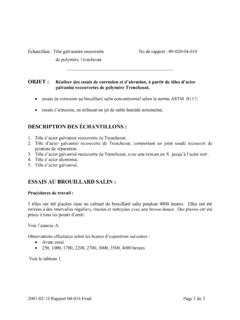
3 The supporting soil beneath the pipe,generally referred to as the foundation, must provide both longitudinal and lateralsupport. INSTALLATION &CONSTRUCTIONPROCEDURESCHAPTER 7 The portion of the foundation in contact with the bottom of the structure isreferred to as the bedding. Depending upon the size and type of structure, thebedding may either be flat or shaped. Soft FoundationEvaluation of the CONSTRUCTION site may require subsurface exploration to detectundesirable foundation material, such as soft material (muck) or rock ledges. Zonesof soft material give uneven support and can cause the pipe to shift and settle non-uniformly after the embankment is constructed. Thus material of poor or non-uniform bearing capacity should be removed and replaced with suitable compactedfill to provide a continuous foundation that uniformly supports the imposedpressures. The bedding may then be prepared as for normal foundations.
4 Figure the treatment of soft is important that poor foundation material be removed, for a distance on eitherside of the pipe, and replaced with compressed backfill. Otherwise, that material willsettle under the load of the backfill alone and actually increase the load on the is referred to as negative soil FoundationsIf rock ledges are encountered in the foundation, they may serve as hard points thattend to concentrate the loads on the pipe. Such load concentrations are undesirable310 STEEL DRAINAGE AND HIGHWAY CONSTRUCTION PRODUCTSF igure Yielding foundation treatment may be specified for larger pipestructures, and/or large invert radii. By selective excavation, it ispossible to set up relative (not actual) motion (as indicated byarrows), thereby improving soil-structure INSTALLATION AND CONSTRUCTION PROCEDURES311 Backfill placement and detention tank installation in the City of DRAINAGE AND HIGHWAY CONSTRUCTION PRODUCTS since they can lead to distortion of the structure.
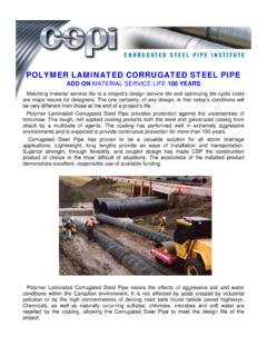
5 Thus large rocks or ledges must beremoved and replaced with suitable compacted fill before preparing the pipebedding. Furthermore, when the pipe foundation makes a transition from rock tocompressible soil, special care must be taken to provide for reasonably uniformlongitudinal support. Figure illustrates the treatment for rock foundations andtransition BeddingWith flat bedding, which is usually standard for factory-made round pipe, the pipe isplaced directly on the fine-graded upper portion of the foundation. Soil must then becompacted under the haunches of the structure in the first stages of bedding concept for pipe-arch structures also relates to large diameter andunderpass shapes. For these structures, the bedding should be shaped to theapproximate contour of the bottom portion of the structure. Alternatively, thebedding can be shaped to a slight V-shape. Shaping the bedding affords a moreuniform support for the relatively flat structures.
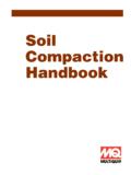
6 The shaped portion need not extendFigure Rock foundations and transition of pipe foundations from compressible soils to rock. Excavate rock and compressible soil intransition section to provide reasonably uniform longitudinal pipe support and minimum :Section B-B is applicable to all continuous rock INSTALLATION AND CONSTRUCTION PROCEDURES313 Figure Typical backfill envelope for pipe-arch or long span Typical vee-shaped bedding for pipe-arches and large bedding detail with grade bottom graded in shallow the entire bottom, but must be wide enough to permit the efficient compactionof the backfill under the remaining haunches of the illustrates shaped bedding for a pipe-arch. Note that the soil besideand below the corners of a pipe-arch must be of excellent quality, highly compacted,and thick enough to spread and accommodate the high reaction pressures that candevelop at that the bedding is flat or shaped, the upper 50 to 100 mm layer should berelatively loose material so that the corrugations can seat in the bedding.
7 Thematerial in contact with the pipe should not contain gravel larger than 75 mm, frozenlumps, chunks of highly plastic clay, organic matter, or deleterious DRAINAGE AND HIGHWAY CONSTRUCTION PRODUCTSC amber in the grade under high fills, or on a foundation that may settle, should beconsidered in base preparation. Camber is simply an increase in the foundation orbedding elevation at the center of a culvert above a straight line connecting its ends(the intended grade or slope of the pipe). The objective is to shape and/or elevate thegrade to assure a proper flow line after settlement takes place. This forethought willprevent a sag in the middle of the culvert that might pocket water, or reduce capacitybecause of sedimentation. Generally, enough camber can be obtained by placing thebase for the upstream half of the pipe on an almost flat grade, and the downstream halfon a steeper than normal grade. The greater load at the center of the embankment, andthe corresponding settlement, will result in the desired positive slope after fullconsolidation.
8 Soils engineering techniques are available to predict the amount ofcamber required for unusual conditions. It is possible to obtain a camber equal to one-half of one percent of the length of the culvert without special fittings. For structuresunder high fills, the ordinates of this curve should be determined by a soils illustrates camber for a pipe under a high OF CORRUGATED STEEL PIPE AND PIPE-ARCHU nloading and HandlingAlthough corrugated steel drainage structures will withstand rough handling withoutdeformation, they should be handled with reasonable care. Pipe should never bedumped directly from a truck bed while unloading, but should be lifted or rolled toprotect the galvanized surface. Polymer laminated pipe should be secured and liftedonly, using fabric slings. Dragging the structures at any time may damage thecoatings and jeopardize durability. Also, avoid striking rocks or hard objects whenlowering pipe into the pipe has been ordered with lifting lugs, utilize them by using wire ropeslings equipped with hooks.
9 This simplifies installation, but rough handling shouldstill be avoided. Since corrugated steel structures are relatively light in weight, theycan be handled with simple, light equipment. If necessary, a small crew can lowerpipe into trenches by means of rope Camber allows for settlement of a culvert under high 3000 mm and smaller are easier to camber, as are thelighter wall INSTALLATION AND CONSTRUCTION PROCEDURES315 AssemblyThe usual methods of joining two or more lengths of pipe or pipe-arch is by meansof steel connection bands. The bands engage the ends of each pipe section, and areplaced to overlap equally amounts of each pipe providing an integral and many years, joints for corrugated steel pipe were specified with full detailsand dimensions, based on traditional devices. Little thought was given to thefunctional requirements for joints on individual in the early 1980s, rational structural requirements were developed forfield joints in corrugated steel pipe.
10 Extensive research towards realisticperformance requirements, in terms of moment, shear, tension and degree oftightness, was conducted by California Transportation (CALTRANS).From this, rational mechanical and structural performance requirements weredeveloped by the Bridge Design Code Committee of the American Association ofState Highway and Transportation Officials (AASHTO). These performancerequirements are published in Division II, Section , of the current edition of theAASHTO Bridge CSP into stream diversion DRAINAGE AND HIGHWAY CONSTRUCTION PRODUCTSThe AASHTO Specifications provide an excellent description of joint properties include shear strength, moment strength, tensile strength, jointoverlap, soil tightness and watertightness. Their recommended minimumrequirements depend on whether the pipe is being installed in erodible or non-erodible basic corrugated coupler systems in general use in Canada, as shown inChapter 2, were tested by CALTRANS and were formed to meet all of theperformance requirements.