Transcription of Chapter 8: Mat Foundations - Islamic University of Gaza
1 Civil Engineering Department: Foundation Engineering (ECIV 4052) Engr. Yasser M. Almadhoun Page 1 Chapter 8: Mat Foundations Introduction Under normal conditions, square and rectangular footings are economical for supporting columns and walls. However, under certain circumstances, it may be desirable to construct a footing that supports a line of two or more columns. These footings are referred to as combined footings . When more than one line of columns is supported by a concrete slab, it is called a mat foundation. Combined footings can be classified generally into four categories: (1) rectangular combined footing (2) Trapezoidal combined footing (3) Strap footing Mat Foundations are generally used with soil that has a low bearing capacity. This Chapter has been demonstrated in two distinct parts, which are as given as under: Part A: Geotechnical design, and Part B: Structural design.
2 Civil Engineering Department: Foundation Engineering (ECIV 4052) Engr. Yasser M. Almadhoun Page 2 Part A: Geotechnical Design The geotechnical design of Foundations will be illustrated for isolated and combined footings in the next following sections. A. isolated Footing Most economical type. It can be rectangular , circular or square. It is preferred that the shape of the footing matches the shape of column above. A = B L B. Combined Footing (1) rectangular combined footing In such a case, two or more columns can be supported on a single rectangular foundation. If the net allowable soil pressure is known, the size of the foundation (B L) can be determined in the following manner: Civil Engineering Department: Foundation Engineering (ECIV 4052) Engr.
3 Yasser M. Almadhoun Page 3 a. No property line ( extension is permitted from both sides) Civil Engineering Department: Foundation Engineering (ECIV 4052) Engr. Yasser M. Almadhoun Page 4 b. One property line ( extension is permitted from one side only) =2( + 12) 2= 1 12 Civil Engineering Department: Foundation Engineering (ECIV 4052) Engr. Yasser M. Almadhoun Page 5 c. Two property line ( extension is obstructed from both sides) = 2 1 1+ 2 = 2 12 If > / , use the following equation: = ( )=4( 1+ 2)3 ( 2 ) = Otherwise, use the following equation: = ( )= (1+6 ) = X Civil Engineering Department: Foundation Engineering (ECIV 4052) Engr.
4 Yasser M. Almadhoun Page 6 (2) Trapezoidal combined footing Trapezoidal combined footing is sometimes used as an isolated spread foundation of columns carrying large loads where space is tight. The size of the foundation that will uniformly distribute pressure on the soil can be obtained in the following manner: a. No property line ( extension is permitted from both sides) = 1+ 22 ( .1) Civil Engineering Department: Foundation Engineering (ECIV 4052) Engr. Yasser M. Almadhoun Page 7 + 2=( 1+2 2 1+ 2) 3 ( .2) Solving equations (1) and (2): 1= 2= b. One property line ( extension is permitted from one side only) = 1+ 22 (.)
5 1) + 12=( 1+2 2 1+ 2) 3 ( .2) Civil Engineering Department: Foundation Engineering (ECIV 4052) Engr. Yasser M. Almadhoun Page 8 Solving equations (1) and (2): 1= 2= c. Two property line ( extension is obstructed from both sides) = 1+ 22 ( .1) + 12=( 1+2 2 1+ 2) 3 ( .2) Solving equations (1) and (2): 1= 2= Civil Engineering Department: Foundation Engineering (ECIV 4052) Engr. Yasser M. Almadhoun Page 9 (3) Strap footing (Cantilever footing) Cantilever footing construction uses a strap beam to connect an eccentrically loaded column foundation to the foundation of an interior column.
6 Cantilever footings may be used in place of trapezoidal or rectangular combined footings when the allowable soil bearing capacity is high and the distances between the columns are large. = 1+ 2= 1+ 2 Civil Engineering Department: Foundation Engineering (ECIV 4052) Engr. Yasser M. Almadhoun Page 10 = 2 1= / = + 12 12 = 1= ( + ) 2= 1 1= 1 ( ) 2= 2 ( ) C. Mat Foundation (Raft Foundation) It is a combined footing that may cover the entire area under a structure supporting several columns and walls. Mat Foundations are sometimes preferred for soils that have low load-bearing capacities, but that will have to support high column or wall loads. Under some conditions, spread footings would have to cover more than half the building area, and mat Foundations might be more economical.
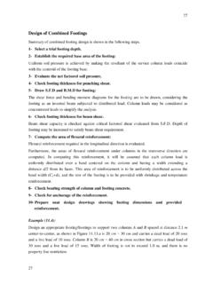
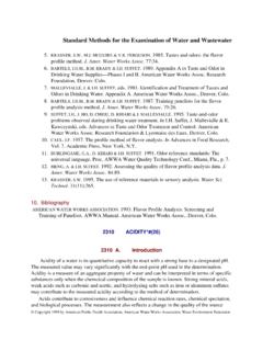
7 Common types of mat foundation Several types of mat Foundations are currently used. Some of the common ones are listed as given under: Flat plate: the mat is of uniform thickness (Figure a). Flat plate thickened under columns (Figure b). Beams and slab: the beams run both ways, and the columns are located at the intersection of the beams (Figure c). Flat plates with pedestals (Figure d). Slab with basement walls as a part of the mat: the walls act as stiffeners for the mat (Figure e). Civil Engineering Department: Foundation Engineering (ECIV 4052) Engr. Yasser M. Almadhoun Page 11 Comparison of isolated foundation and mat foundation The Figure below shows the difference between the depth Df and the width B of isolated Foundations and mat Foundations .
8 Civil Engineering Department: Foundation Engineering (ECIV 4052) Engr. Yasser M. Almadhoun Page 12 Bearing capacity of mat foundation The gross ultimate bearing capacity of a mat foundation can be determined by the same equation used for shallow Foundations (see Section in textbook), or: = + +12 The term B in the load-bearing capacity equation is the smallest dimension of the mat. The net ultimate capacity of a mat foundation is: ( )= A suitable factor of safety should be used to calculate the net allowable bearing capacity: For mats on clay, the factor of safety should not be less than 3 under dead load or maximum live load. However, under the most extreme conditions, the factor of safety should be at least to 2.
9 For mats constructed over sand, a factor of safety of 3 should normally be used. Under most working conditions, the factor of safety against bearing capacity failure of mats on sand is very large. For saturated clays with =0 and a vertical loading condition ( =0), the net ultimate bearing capacity is: Hence, the net ultimate bearing capacity ( ) is: Or, the load-bearing capacity can be obtained based on Standard Penetration Test (SPT) and may be expressed as: Civil Engineering Department: Foundation Engineering (ECIV 4052) Engr. Yasser M. Almadhoun Page 13 In English units, the previous equation may be expressed as: Recall that, generally, shallow Foundations are designed for a maximum settlement of 25 mm (1 in.)
10 And a differential settlement of three-fourths of the tolerable settlement, which is about 19 mm ( in.). However, the width of a raft foundation is larger than those of the isolated spread footings . The depth of significant stress increase in the soil below a foundation depends on the width of the foundation. Hence, for a raft foundation, the depth of the zone of influence is likely to be much larger than that of a spread footing. Thus, the loose soil pockets under a raft may be more evenly distributed, resulting in a smaller differential settlement. Accordingly, the customary assumption is that, for a maximum raft settlement of 50 mm (2 in.), the differential settlement would be 19 mm ( in.). The net pressure applied on a foundation (as shown in the Figure below) may be expressed as: Civil Engineering Department: Foundation Engineering (ECIV 4052) Engr.