Transcription of CHAPTER IX. Design-SWITCHYARD - …
1 CHAPTER IX. Design-SWITCHYARD A. STRUCTURAL . 104. GENERAL. The switchyard is located approximately 850 feet southwest of the right abutment of the dam, and approximately 170 feet higher than the top of the dam. The fill for embankment ranges up to 27 feet in depth and the cut for excavation ranges up to 24 feet in depth. Since the embankment slopes, as constructed, consisted primarily of fine sand, a 12-inch layer of pi6run grave! was placed on the slopes for protection from wind and water erosion. As an additional protection against water erosion, a curb, gutter, and drain system was later constructed. 105. CONCRETE FOUNDATIONS. All pad and stem type foundations were designed for a gross toe pressure not to exceed 3,000 pounds per square foot and a factor of safety against uplift and overturning of not less than Rock-type foundations were extended a minimum 12 inches into rock to resist shear forces. Anchor bars were designed for a maximum tensile stress of 16,000 pounds per square inch and were embedded to a depth so that the rock shear stress does not exceed 300 pounds per square foot.
2 106. CONCRETE FOOTINGS FOR APPROACH TOWERS. The footings for towers C1-T2, C2-T2, C3-T2, and C4-T2 were designed as rock-type footings. To resist the shear forces, the footings were extended a minimum of 12 inches into rock. Anchor bars were designed for a maximum tensile stress of 16,000 pounds per square inch and were embedded to a depth so that the rock shear stress does not exceed 300 pounds per square foot. 'The footings for rim towers C1 -TI, C2-TI, C3-TI, and C4-TI were designed as rock-type footings. To resist shear forces, the footings were extended a minimum of 24 inches into rock. Anchor bars were designed for a maximum tensile stress of 16,000 pounds per square inch and were embedded a minimum of 25 feet into rock to attain maximum strength in the bedrock by spanning the bedding planes and stress relief joints which are present near the edge of the canyon rim. 107. CONTROL CABLE TUNNEL. The control cable tunnel extends approximately 1,280 feet from a lower portal near the powerplant to an entry structure in the switchyard .
3 The control tunnel has concrete walls and a pneumatically applied mortar roof, except for approximately 100 feet at the portal end which has reinforced concrete walls and roof. To relieve any phreatic pressure, the floor of the tunnel was left unpaved. 1. Transformer Circuits and Switch yards 108. LOCATION. The four overhead transformer circuits, three at 345 kilovolts and one at 230 kilovolts, emanate from steel takeoff brackets on the powerplant wall at approximate elevation The three 345-kilovolt circuits pass under the Glen Canyon Bridge and rise to rim towers C1 -TI, C2-TI, and C3-TI (figs. 206, 207, and 208) on the west canyon rim. From these rim towers, the circuits proceed through backup towers C1-T2, C2-T2, and C3-T2 and then to the 345-kilovolt takeoff structure (fig. 209) in the switchyard . The 230-kilovolt circuit also passes under the bridge to rim tower C4-TI on the east canyon rim, thence across the canyon to tower C4-T2 which accommodates the span to the 230-kilovolt takeoff structure in the switchyard (fig.)
4 210). The switchyard is located downstream from the dam, near the west canyon rim and south of the State highway and the bridge. This location'provides for the most flexible arrangement for the several transmission line approach spans to the 345-, 230-, 69, and 25-kilovolt yards and to the future 138-kilovolt yard. 109. STEEL STRUCTURES FOR TRANSFORMER CIRCUITS. (a) Takeoff series of eight three-bay takeoff brackets were mounted on the exposed steel column flanges of the powerplant wall columns at a suitable elevation for required electrical clearances and conductor arrangement to the transformers and lightning arresters on the powerplant deck. This essentially provided a continuous run of line attachment beams, with the exception of breaks in continuity as imposed by expansion joints in the powerplant wall. With this takeoff bracket arrangement, sufficient line attachment spacing was realized for lines taking off at maximum 30' horizontal and 37' vertical line angles.
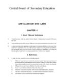
5 The attachment spacing was correlated with phase spacing at the canyon rim towers to meet electrical requirements for midspan circuit spacing and phase separations. Closely related to the takeoff bracket design was the problem of maintaining safe electrical clearances to design switchyard design Figure 208 -Artist's conception of 345-kilovolt tower C 1 -T1 on canyon rim. P557-0-36377. -- SWITCHYAR D design switchyard the downstream bridge arch, canyon walls, and canyon rims. Using the physical properties of a 2,167,000-circular-mil ACSR (Kiwi) conductor for the three 345-kilovolt circuits and 954,000-circular-mil ACSR (Cardinal) conductor for the one 230-kilovolt circuit, conditions of either sideswing from a wind acting transversely, or the generally accepted elliptical movement in space from possible "galloping" were taken into account. These studies entailed careful positioning of the catenaries of conductors from the takeoff brackets to the rim towers.
6 Also considered in the design was a maximum direct line tension of 16,000 pounds per conductor phase, with 1-inch radial ice at 40 pounds per cubic foot and no wind at 30' F. Because of these conductor problems at midspan, it was necessary to make concurrent designs on the powerplant takeoff brackets and canyon rim towers. The beams of the takeoff brackets were designed to withstand bending stresses due to the 16,000-pound direct line tensions and torsional stresses induced by the vertical line loads acting in an offset position from centerline of the beam section. Using these line loads, coupled with transverse loads due to a wind, a rigid-frame analysis was executed for designing the beam to bracket arm connections and the bracket arm to powerplant wall column connections. (b) 345- Kilovolt Rim Towers C 1-T 1, C2- T 1, and towers (figs. 206 and 207) are the first in the United States using the new extra-high-strength structural steel shapes.
7 The towers-two are 210 feet high and one is 190 feet three separate types of steel materials. These are heat-treated alloy steel of extra high strength, minimum yield point of 100,000 pounds per square inch; high-strength low-alloy steels, ASTM A 440, minimum yield point of 50,000 pounds per square inch; and standard-strength carbon steeis, ASTM A 36, minimum yield point of 36,000 pounds per square inch. The legs of the two 210-foot towers from the ground to the 145-foot level and the legs of the 190-foot tower to the 125-foot level are of the extra-high-strength steel shapes; the remaining 65 feet of the legs of the structures and the entire web system and chords are the A 440 steel. The cage, ladders, and walkway platform supports are the A 36 steel. The walkway platforms are aluminum, in accordance with Federal Specifications RR-G-661a, type I, for a loading of 50 pounds per square foot. Each tower supports a 345,000-volt transformer circuit emanating from the 900,000-kilowatt Glen Canyon Powerplant at the toe of the dam.
8 The 3-phase transformer circuits, ranging from 900 to 1,400 feet in horizontal span length, pass under the Glen Canyon Bridge, a short distance downstream from the dam, and rise 800 feet from the powerplant to the rim towers. Many unprecedented problems were encountered in the design of these rim towers. Studies were conducted to determine the special structure design characteristics required to overcome the many difficulties presented in reaching a satisfactory solution for transmitting electrical power out of the canyon, as mentioned in subsection (a) above. The heights of the rim towers were determined by an acceptable conductor clearance under the bridge and over the canyon rim edge. The structures are located at safe distances from the canyon rim, consistent with foundation safety, adequate conductor spacing, and span length limitations. A minimum of 25 feet was permitted from the intercept of the canyon wall plane with the ground surface to the tower column legs.
9 These requirements necessitated a cantilever design concept for the conductor attachment beams on the structures. From the resolution of these requisites, effective outlines of the structures were established with the most efficient use of both ground and air space. The structures were also designed to withstand a wind, plus an increase in wind pressure of 10 percent due to structure height, with an exposure factor of applied simultaneously to both columns. The analysis was performed for all possible combinations of intact and broken wire assumptions, including full dead end on either side of the structures, plus maximum wind from any direction and with a factor of safety of Based on preliminary design computations, several types of built-up sections, using high-strength structural steel angles and plates bolted together, were tried and compared with the extra-high-strength steels. The use of the extra-high-strength steels resulted in a substantial savings in weight of material and fabrication and erection time.
10 The proper use of the three different strengths of steel resulted in far more economical structures than normally could be attained with one type of steel. Weight saved by the extra-high-strength steel? was 50 percent in those portions of the structures where they were used. The weight reduction resulted in a 20 percent savings in the total cost of the structures. The structures were designed for the tabulated loads shown on figure 206. The tower portion of the structures was analyzed as an indeterminate, three-story, single-bay portal frame. The cantilever design portion was analyzed as indeterminate frames in both the plan and elevation views. The reactions from the analysis of the cantilever portion of the structure were applied to the tower column as additional loads; also, the moment reaction from the cantilever frame in plan caused a torsional load on the tower columns. Another very difficult and highly indeterminate problem was the torsional distribution at the top of the columns.