Transcription of Characteristics and Applications of Hitachi H-25 …
1 Hitachi Review Vol. 57 (2008), No. 6 273 Characteristics and Applications of Hitachi H-25 GasTurbineOVERVIEW: More than 100 orders have been placed for Hitachi H-25 gasturbines from both Japan and various other countries, because of theirexceptionally high reliability and efficiency in their class. In addition, theycan be used for a wide range of Applications , from power and generalindustrial use to utilization in oil and gas fields. The H-25 is characterizedas being heavy-duty, highly reliable, and applicable to cogeneration andcombined cycle operations, resulting in higher operational efficiency of theentire system, for which it is highly acclaimed. In one recent applicationwhere the worksite was located far from the power supply system, severalH-25 gas turbines were used to form an island operation system that wasnot linked to the main power system.
2 In another application, an H-25 gasturbine was used as a power supply for driving a motor, instead of themechanical drive system usually based on a small gas turbine . Suchapplications have been adopted due to the high reliability of the H-25 gasturbine. Hitachi , Ltd. has continued to enhance its H-25 gas turbine as atype of power supply equipment, and thus has contributed to the fields inwhich it has been AraiShinji UseShunichi HiroseShinichi NagaiMitsuo TeranishiKenji KaminoINTRODUCTIONTHE H-25 gas turbine is an open, simple-cycle, singleshaft gas turbine of the 30-MW H-25 gas turbine offers the followingcharacteristics:(1) It is heavy-duty, highly reliable, and ideally suitedfor continuous operation.
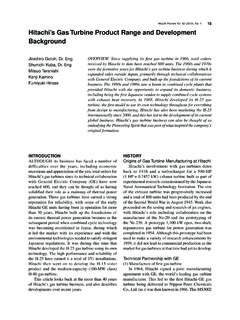
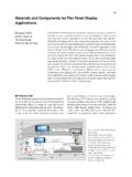
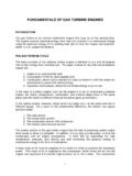
3 (2) The system start-up time when used in a simplegas turbine cycle is between 15 and 20 min fromignition to reaching the rated load, and thus shorterthan that in conventional steam power generation. Itis therefore applicable for DSS (daily start-up and shut-down) and peak Applications .(3) Based on modern turbine cooling and compressortechnologies, the H-25 achieves the highest level ofthermal efficiencies in the heavy-duty 30-MW is also one of the models that has achieved the highestlevel of efficiency as a cogeneration system combinedFig. 1 H-25 gas turbine andGeneral Overview of Sakhalin IIProject in delivered four H-25 gasturbine generation equipment unitsto the Sakhalin Energy InvestmentCo.
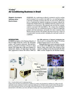
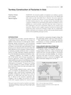
4 , Ltd., for use in a land-side plantthat processes gas and oil extractedfrom the seabed off the eastern shoreof Sakhalin Island in and Applications of Hitachi H-25 gas turbine 274natural performance is remarkable for a heavy-dutygas turbine of the 30-MW class. When combined witha steam turbine , the system offers the highest level ofcombined cycle efficiency a gross thermalefficiency of 50% LHV or Composition of H-25 Gas TurbineFig. 3 (b) shows the equipment composition andperformance of the H-25 gas turbine . The turbine canbe roughly divided into 17 axial flow compressors, 10cannular combustors, and three stage bearings have a forced lubricating system. Thejournal bearings are No.
5 1 on the turbine side and on the compressor side, while the thrust bearingsare on the compressor side. These are tilting casing is horizontally split for both thecompressor and turbine sides, while the support isdesigned to absorb thermal terms of exhaust, a side exhaust was previouslythe mainstream. However, in recent years, the axialwith an HRSG (heat recovery steam generator) and acombined cycle equipped with a steam turbine .(4) The use of a horizontally split casing and a multi-can combustor ensures its high maintainability, andenables the on-site replacement of hot gas path parts.(5) The adoption of various combustor technologiesmakes the system adaptable for use of light oil, LNG(natural gas), LPG (liquefied petroleum gas), and otherfuels.
6 Moreover, the application of a wet/dry low-NOxcombustor enables low- NOx environmental measuresto be fuel diversification technology, Hitachi isactively committed to using off-gas, COG (coke ovengas), coal gas, dimethyl ether, and other special rest of this report describes H-25 gas turbine shistory, specifications, and examples of its Applications (see Fig. 1).HISTORY OF H-25 GAS TURBINEIn 1988, the first H-25 unit was completed anddelivered to the Tokuyama Oil Refinery of IdemitsuKosan Co., in 1990, Hitachi delivered the first H-15 unit a scaled down model to the Research Union forIntegrated Coal Gasification Combined Cycle, and thusexpanded its scope of about a decade after delivery of its first unit,the H-25 has been mainly used for cogenerationapplications in domestic petrochemical on its proven capabilities and track record duringthat period, Hitachi delivered the first unit for overseasuse to South Korea in 2000.
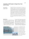
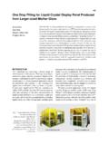
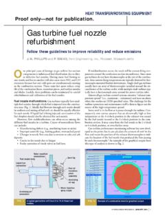
7 Since then, many moreunits have been delivered to various parts of the world(see Fig. 2).The 20th anniversary of the first H-25 unit everbeing delivered will happen this year (2008). Givenits widely recognized high performance and reliability,the unit has received more than 100 cumulative orders,with more than 70 units now in commercial , the total operation time of these turbineslargely exceeds million hours. As illustrated in , the product continues to run steadily AND EQUIPMENTCOMPOSITION OF H-25 GAS TURBINEP erformance of H-25 Gas TurbineFig. 3 (a) shows the performance of the H-25 andH-15 under ISO (International Organization forStandardization) conditions. The H-25 achieves anoutput of 31 MW and a gross thermal efficiency LHV (lower heating value) when fired withFig.
8 2 H-25 Gas Turbines Previously are the H-25 gas turbines delivered both domesticallyand abroad. H-25 gas turbines have been steadily running invarious environments ranging from the extreme cold in Russia( 48 C) to the intense heat of Iraq (54 C).Year of operation start-upCumulative unitsUnits198819891990020406080100199119 9219931994199519961997199819992000200120 022003200420052006200720082009 First exported unit put into operationOverseas promotion launchedOutside Japan: 80 total unitsTotal: 104 unitsIn Japan: 24 total unitsH-25H-15In JapanOutside Japan(as of Sep. 2007) Hitachi Review Vol. 57 (2008), No. 6 275 TURBINET urbine Application TechnologyThe H-25 turbine consists of three impulse illustrated in Fig.
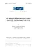
9 5 (a), the first stage bucket isdesigned as a multi-pass cooling bucket, with staggeredribs developed by Hitachi to increase the turbine buckets are made of nickel-base alloysthat have extremely high temperature strengths. Thefirst stage turbine bucket has a TBC (thermal barriercoating), as illustrated in Fig. 5 (b), to cool the metalsurfaces of the combination of impingement cooling, filmcooling, and pin fin cooling are applied for the firstflow exhaust has also been used to increase axial flow type is designed so that the front shaftof the compressor is connected to a reduction gearequipped with an accessory gear. The start-up motoris then connected to the generator.
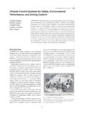
10 The lubricating oiltank is either installed separately as an off-base skidor arranged compactly, also functioning as the basisfor the reduction gear as shown in Fig. 3 (b).COMPRESSORC ompressor Application TechnologyThe axial compressor for the H-25 gas turbine has17 stages and a pressure ratio of 15. The compressoris equipped with an IGV (inlet guide vane) at theinlet, and its hydraulic drive allows it to control front stages of the compressor entail a highMach number. A supercritical arc blade, multiplecircular arc blade, and double circular arc blade areapplied to control any loss, as shown in Fig. 4. Therotor and stator blades are made of 12Cr-Nb steel and12Cr steel, and given a corrosion-proof system is designed so that 6-stage and 13-stageair extractions are used to discharge air to prevent froma rotating stall during start-up.