Transcription of Charts of Theoretical Stress-Concentration Factors K*
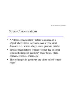
1 1026 Mechanical Engineering DesignTable A 15 Charts of Theoretical Stress-Concentration Factors K*tFigure A 15 1 Bar in tension or simplecompression with a transversehole. 0=F/A, whereA=(w d)tand tis A 15 2 Rectangular bar with atransverse hole in bending. 0=Mc/I, whereI=(w d)h3 `d/h = = A 15 3 Notched rectangular bar intension or simple compression. 0=F/A, where A=dtand tis the Tables1027 Table A 15 Charts of Theoretical Stress-Concentration Factors K*t(Continued) = ` = = A 15 4 Notched rectangular bar inbending. 0=Mc/I, wherec=d/2, I=t d3/12, and tisthe A 15 5 Rectangular filleted bar intension or simple compression.
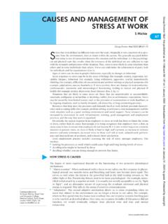
2 0=F/A, where A=dtand tis the A 15 6 Rectangular filleted bar inbending. 0=Mc/I, wherec=d/2, I=t d3/12, tis thethickness.* Factors from R. E. Peterson, Design Factors for stress Concentration, Machine Design, vol. 23, no. 2, February 1951, p. 169; no. 3, March1951, p. 161, no. 5, May 1951, p. 159; no. 6, June 1951, p. 173; no. 7, July 1951, p. 155. Reprinted with permission from Machine Design, a Penton Media Inc. publication.(continued )1028 Mechanical Engineering DesignTable A 15 Charts of Theoretical Stress-Concentration Factors K*t(Continued)Figure A 15 7 Round shaft with shoulder filletin tension.
3 0=F/A, whereA= d2 A 15 8 Round shaft with shoulder filletin torsion. 0=T c/J, wherec=d/2and J= d4 A 15 9 Round shaft with shoulder filletin bending. 0=Mc/I, wherec=d/2and I= d4 = = = Tables1029 Table A 15 Charts of Theoretical Stress-Concentration Factors K*t(Continued)Figure A 15 10 Round shaft in torsion withtransverse A 15 11 Round shaft in bending with a transverse hole. 0=M/[( D3/32) (d D2/6)], D316dD26= (approx)ADKts, AKts, A 15 12 Plate loaded in tension by a pin through a hole. 0=F/A,where A=(w d)t. Whenclearance exists, increase Kt35 to 50 percent.(M. M. Frochtand H. N.)
4 Hill, Stress-Concentration Factors arounda Central Circular Hole in aPlate Loaded through a Pin inHole, J. Appl. Mechanics, vol. 7, no. 1, March 1940,p. A-5.) = $ = (continued )* Factors from R. E. Peterson, Design Factors for stress Concentration, Machine Design, vol. 23, no. 2, February 1951, p. 169; no. 3, March1951, p. 161, no. 5, May 1951, p. 159; no. 6, June 1951, p. 173; no. 7, July 1951, p. 155. Reprinted with permission from Machine Design, aPenton Media Inc. A 15 Charts of Theoretical Stress-Concentration Factors K*t(Continued)* Factors from R. E. Peterson, Design Factors for stress Concentration, Machine Design, vol.
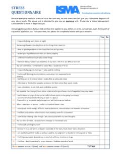
5 23, no. 2, February 1951, p. 169; no. 3, March 1951,p. 161, no. 5, May 1951, p. 159; no. 6, June 1951, p. 173; no. 7, July 1951, p. 155. Reprinted with permission from Machine Design, a PentonMedia Inc. Engineering DesignFigure A 15 13 Grooved round bar in tension. 0=F/A, where A= d2 A 15 14 Grooved round bar in bending. 0=Mc/l, where c=d/2and I= d4 A 15 15 Grooved round bar in torsion. 0=T c/J, where c=d/2andJ= d4 = = = Tables1031 Table A 15 Charts of Theoretical Stress-Concentration Factors K*t(Continued)Figure A 15 16 Round shaft with flat-bottomgroove in bending and/ortension. 0=4F d2+32M d3 Source:W.
6 D. Pilkey,Peterson sStress-Concentration Factors ,2nd ed. John Wiley & Sons,New York, 1997, p. (continued )1032 Mechanical Engineering DesignTable A 15 Charts of Theoretical Stress-Concentration Factors K*t(Continued)Figure A 15 17 Round shaft with flat-bottomgroove in torsion. 0=16T d3 Source:W. D. Pilkey,Peterson sStress-Concentration Factors ,2nd ed. John Wiley & Sons,New York, 1997, p. Tables1033 Table A 16 Approximate Stress-Concentration Factor Ktfor Bending of a RoundBar or Tube with aTransverse Round HoleSource:R. E. Peterson, Stress-Concentration Factors ,Wiley,New York, 1974, pp.
7 146, nominal bending stress is 0=M/Znetwhere Znetis a reducedvalue of the section modulus and is defined byZnet= A32D(D4 d4)Values of Aare listed in the table. Use d=0for a solid (continued )1034 Mechanical Engineering DesignTable A 16 (Continued)Approximate Stress-Concentration Factors Ktsfor a Round Bar or Tube Having a Transverse Round Hole andLoaded in TorsionSource:R. E. Peterson, Stress-Concentration Factors ,Wiley, New York, 1974, pp. 148, maximum stress occurs on the inside of the hole, slightly below the shaft surface. The nominal shear stress is 0=T D/2 Jnet,where Jnetis a reduced value of the second polar moment of area and is defined byJnet= A(D4 d4)32 Values of Aare listed in the table.
8 Use d=0for a solid Engineering DesignLoading Factor kcWhen fatigue tests are carried out with rotating bending, axial (push-pull), and torsionalloading, the endurance limits differ is discussed further in Sec. 6 , we will specify average values of the load factor askc={ (6 26)Temperature Factor kdWhen operating temperatures are below room temperature, brittle fracture is a strongpossibility and should be investigated first. When the operating temperatures are higherthan room temperature, yielding should be investigated first because the yieldstrength drops off so rapidly with temperature; see Fig.}
9 2 9. Any stress will inducecreep in a material operating at high temperatures; so this factor must be considered ={ a+ (b x)axis ={ > = = 6 Areas of CommonNonrotating StructuralShapes17 Use this only for pure torsional fatigue loading. When torsion is combined with other stresses, such asbending, kc=1and the combined loading is managed by using the effective von Mises stress as in Sec. 5 :For pure torsion, the distortion energy predicts that (kc)torsion= Failure Resulting from Variable Loading291 Finally, it may be true that there is no fatigue limit for materials operating at high tem-peratures.}}
10 Because of the reduced fatigue resistance, the failure process is, to someextent, dependent on limited amount of data available show that the endurance limit for steelsincreases slightly as the temperature rises and then begins to fall off in the 400 to 700 Frange, not unlike the behavior of the tensile strength shown in Fig. 2 9. For this reasonit is probably true that the endurance limit is related to tensile strength at elevated tem-peratures in the same manner as at room seems quite logical, therefore,to employ the same relations to predict endurance limit at elevated temperatures as areused at room temperature, at least until more comprehensive data become available.