Transcription of CHERRYMAX PROCESS MANUAL
1 CHERRYMAX PROCESS MANUALSLEEVE MATERIALM MONEL+ INCO 600NO ID FOR ALUMINUM+ IDENTIFIESCRES STEM(CR32 XXRIVET ONLY)RAD MONELRAD MONELOPTIONAL CONFIGURATIONFOR CRES STEMSMIN BLIND CLEARANCEFOR SATISFACTORYINSTALLATIONMIN BLIND CLEARANCEFOR SATISFACTORYINSTALLATIONSLEEVE MATERIALM MONELNO ID FOR ALUM+ IDENTIFIESCRES STEM(CR32 XXRIVET ONLY)SPS Fastener Division, a PCC CompanyCONTENTSP roduct Description ..2 CHERRYMAX Rivet Features ..2 CHERRYMAX Rivet Benefits ..2 Rivet Availability ..3 Tooling Availability ..3 Installation Sequence ..3 CHERRYMAX Rivet Tool Selection ..5 CHERRYMAX Installation ..6 Hole preparation ..7 Correct Grip Measurement ..11 Proper Sealant Application ..12 Rivet Shaving ..13 Inspection of Installed CHERRYMAX Fasteners.
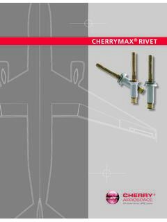
2 13 Rivet Installation Troubleshooting ..16 Rivet Removal ..17 CHERRYMAX Tooling ..20 Extensions, Adapters & Accessories ..22 Tool Troubleshooting ..23 Service Accessories ..25 Tool & Repair Service ..25 Decimal Equivalent Chart ..26 NAS vs. CHERRYMAX Cross-Reference List ..27 For assistance or further information call Cherry Aerospace Technical Services at 714-850-6022 or visit DESCRIPTIONCHERRYMAX RIVET FEATURESThe CHERRYMAX rivet is a reliable, high strength structural fastener widely used in the aircraft industry. It features the safe-lock locking collar for reliable joint integrity It meets the requirements of CHERRYMAX rivet consists of four components:1. A fully serrated stem with break notch, shear ring and integral grip adjustment2.
3 A driving anvil which acts as a tool, setting the locking collar in place3. A locking collar that mechanically locks the stem to the rivet sleeve during fastener installation4. A rivet sleeve CHERRYMAX RIVET BENEFITSS imple tooling and increased tool lifeThe driving anvil acts as a setting tool increasing the tool life and allowing the installation of multiple sizes (4,5 and 6 diameters) with one tool. Visual InspectabilityThe CHERRYMAX rivet features a safe-lock locking collar which enhances joint integrity and reliability. Correct installation can be assessed from the visible side due to two features: stem flushness and locking collar formation. This system is approved for use in engine inlets and AVAILABILITYMATERIALSFor 50 KSI shear: 5056 aluminum rivet sleeve with Alloy or Corrosion Resistant Steel stemFor 75 KSI shear: Monel rivet sleeve with Corrosion Resistant Steel stem; INCO 600 sleeve/INCO X-750 stem (for high temperature)DIAMETERS1/8", 5/32", 3/16" and 1/4", nominal and oversize (.)
4 016 over nominal)HEAD STYLES Universal (button head) 100 Flush standard and reduced (NAS1097) 120 Flush UnisinkTOOLING AVAILABILITYA wide variety of tools are available for installing CHERRYMAX fasteners. Light, ergonomic riveters Various types of pulling heads for different applications: 1. For areas with open access: Straight Pulling heads 2. For areas with limited access: Right Angle Offset pulling heads Adaptor extensions Split riveters INSTALLATION SEQUENCE1. Insert rivet into the prepared hole and place pulling head over the stem, pushed against the driving anvil (washer).2. When riveter is actuated, the stem is pulled into the sleeve, deforming the blind end into a When the blind end bulb is fully formed, the shear ring of the stem shears, and starts moving down the stem allowing the stem to complete installation.
5 4. When hitting the driving anvil, the locking collar deforms and fills the rivet head recess, locking the sleeve and stem together. The stem then breaks and the top portion is discarded. 4 CHERRYMAX RIVET SELECTIONNUMBERING SYSTEMCR3243 -4 -04 Maximum Grip Length (in 16" increments Rivet Diameter (in 1/32" increments) Head Style/Material Combination (see table)Head StyleMaterial CombinationCountersunk HeadUniversal HeadRivet MaterialStem MaterialNominal CHERRYMAX Nominal CHERRYMAX CR3212CR32135056 ALALLOY STEELCR3222CR32235056 ALCRESCR3522CR3523 MONELCRESO versize CHERRYMAX Oversize CHERRYMAX CR3242CR32435056 ALALLOY STEELCR3252CR32535056 ALCRESCR3552CR3553 MONELCRESCR3852CR3853 INCO 600 INCO X-750 GRIP LENGTHThe last dash number in the part number indicates the maximum grip in 1/16" increments (for example, -04 has a maximum grip of 4/16" = 1/4").)
6 See tables below:Rivet Grip Thickness Range (in.)-01 Minimum Grip GuidelinesMinMaxRivet DiaCherryMAX Universal HeadCR3242 CR3252 CR3552 MS20426 Flush HeadCR3245 CR3255 CR3555 Unisink Head-01*..031N/ .037N/ : For double dimpled sheets, add countersink head height to material * See -01 minimum grip " " TOOL SELECTIONThe shaded areas in the table below show the diameters that each tool / pulling head combination is capable of installing. Cherry recommends using a CHERRYMAX single action riveter for best results. For more information regarding installation tooling combinations, please contact the Cherry Technical Services at of RiveterRiveter ModelPulling HeadAdaptorAll Grip LengthsNominal , Single ActionG273 IncludedNoneG747, G704B G8003H701B-456 NoneH747-456 NoneH781-456 NoneH781A-456 NoneH782 NoneH753A-456 NoneG746AH701B-456 NoneH747-456 NoneH781-456 NoneH781A-456 NoneH782 NoneH753A-456 NoneLockbolt, Hydraulic ReturnG83A G84H701B-456744-3001H747-456744-3001H781 -456744-3001H781A-456744-3001H782744-300 1H753A-456744-3001G84H84A-8 NoneCherrylock, Double ActionG700 CHERRYMAX (See Above)2680B2052G784 CHERRYMAX (See Above)
7 NoneG700H680B200A2680B2052G784H680B200 ANoneNut Plate RivetersG740AH9040-4 CNoneH9040-5 CNoneG715AH9015-3 CNoneH9015-4 CNoneH9015-5C2 None22 Notes: 1. Must remove the bayonette adaptor before using this adaptor; see Tool MANUAL for details. 2. Aluminum version only for this size because of power limitations. 3. This is a hand powered INSTALLATIONIn order to achieve proper fastener installations, make sure to: Prepare and de-burr the holes properly; Select the proper grips for the fasteners to be following pages will describe each of these processes in Make sure the holes are aligned and the structure is properly clamped. Use Tack rivets and/or spring-loaded fasteners to minimize material creep and eliminate sheet Place the rivet in the structure hole.
8 Caution: This should be a clearance fit. Do not force the rivet into the hole! 3. Place the pulling head (Installation tool) onto the rivet stem. Hold the tool coaxial with the hole the fastener is being installed into. Press firmly against head of rivet to minimize head and sheet Depress the trigger (or pump when using hand powered riveters). The rivet clamping action will pull the sheets together, seat the rivet head and break the stem flush with the head of the rivet. Release trigger after the stem breaks. Caution: Make sure to hold the riveter steady and coaxial with the rivet to be installed. A bulb will form on the blind side of the structure. During installation, the broken portion of the stem may be ejected through the back of the riveter; to contain the FOD, use the stem catcher bag (670A20) or the vacuum extraction accessory (RIVAC 220-03).
9 RIGHTWRONGRIGHTWRONG misalignedhole7 HOLE PREPARATIONP roper hole preparation is critical for optimum fastener installation and joint SIZEUse the drill sizes in the table below to produce holes within the required limits. Rivet DiameterDrill DiameterHole Gage Part NumbersNominalOversizeNominal Diameter CHERRYMAX 1/8T172-4T172-4001/8# # # inspect with a Cherry GO/NO-GO gage to assure drilling accuracyOversize Diameter CHERRYMAX 1/8# # # SIZER ivet DiameterMS20426 100 HeadNAS1097 100 HeadC (1/8 ).222 . (5/32 ) .283 . (3/16 ) .350 . (1/4 ) .473 . DiameterUnisink 100 Head120 HeadC (1/8 ). (5/32 ) . (3/16 ) . (1/4 ) 100 .010 R MaxC8 HOLE PREPARATIONDRILLING PROCEDURE 1. Use a clean, sharp, properly ground drill.
10 Improperly ground drills will create oval or oversize Center the drill in the chuck so that the drill will run true. A wobble in the drill will create an oversize Clamp the structure together using spring loaded and hole filling tacking fasteners; this will ensure proper alignment and prevent burrs and chips being generated between the sheets. 4. Hold the drill perpendicular to the surface being drilled. Do not force the drill through the Ground Improperly Ground chipsmisalignmentdrill wobble RIGHT spring-loadedfastenercleanholetackrivet RIGHTWRONG90 WRONG9 HOLE PREPARATIONDE-BURRINGA fter drilling it is advisable to remove the burrs and metal chips generated between the sheets and on the exit side of the structure. Here are some tips for effective and correct de-burring: De-burr carefully, especially on the blind side.