Transcription of Choke Valve Decision Guide
1 Mcilvaine CompanyNorthfield, ILChoke Valve Decision GuideScope and action plan April 5, 2017 Section 1 Table of contentisChokeValve Decision Guide Description and GoalsApplicationsSuppliersChoke DefinitionTypesof chokes Choke DesignProblemsTrim TypesInformation needed for Choke Valve selection Design ConsiderationsWell heads and Christmas treesSection2 Table of ContentsCameronCarterCCIC ircorFlowserveFMCK enintrolMasterFloMokveldN-LinePentairSam sonSubsea chokes International( SCI)2 Choke Valve Decision Guide description and goals Mcilvaine is compiling a continually updated Decision Guide for operators of Choke valves used in oil and gas and other industries for fluid control. Contaminants such as sand integrated into varying mixtures of water, oil, methane and other gases provide both operational and maintenance challenges.
2 The Guide identifies the major applications and then the performance of various designs and various materials for specific The wisdom of the industry is sought in order to make this Guide the best it can be. Input is welcomed from any and all sources. For more information contact Bob Mcilvaine at 784 0012 ext1123 Spectrum of applicationsLocationsfluidsequipmentserv iceTrim shapeDesignflowConditionssurfaceOilWell headsproductionNeedle/diskangleWet CO2 Sub seagasChristmas treereinjectioncageIn-line( control)Sour ( High H2S)chemicalMixtures of crude oil, gas, water, sandManifold plugAxialcontrol but not Choke service?Abrasion,erosion, cavitationpetrochemSteam,CO2In line ball?freezingrefineriesDrilling mud,HydrauicFracturing 4 What are the applications?
3 Why do some companies show axial control and axial Choke as two different products when construction seems similar? What are the uses in chemical and petrochemical? Need info on produced water, fracking, drilling mud and all the applicationsChoke Valve SuppliersCompanyDescriptor axialDescriptoranglesizeMax pressure psigCameron1 -6 10,000 CarterCircorInline Choke ballCCI ( IMIplugFlowserveFMCM aster FlowDiveror ROV retrievable1 -10 20,000 MokveldN-LineDistinguishbetween control and coke2 -16 20,000 PentairSamsonSubsea Chokes4 -10 20,0005 Choke DefinitionAchokevalveisaparticulardesign ofvalvethatraisesandlowersasolidcylinder (calleda"plug"or"stem") (throughtheholesorslots)collidewitheacho theratthecenterofthecagecylinder,thereby dissipatingtheenergyofthefluidthrough"fl owimpingement".)
4 , , , ,slugging,sandproductionandmultiphaseofo il, ,flowpathprofiles, "chokebean"sizeisdetailed, ;thelargertheopening, ,actuatorsmaybea"steppingtype" , ,thewellmay"die" ,oftencalled"beans," (in64ths) + ,tubingsize,amountofgas, function and ,scale,ice, , , ;asgasgoesfrom5000psitoatmosphericpressu re,thegasexpands340fold, ,takeninseriesfrom5000to3000,from3000to5 00and800toatmosphericresultsingasvolume( andvelocity)increasesof136fold(5000psito 3000psi),150fold(3000psito800psi)and54fo ld(500psitoatmospheric).The340foldtotald ropisthesame, with sand -Pentair Oil & Gas Choke valves or Control valves are extensively used in the petrochemical and process industries for the regulation of fluid flow. They experience a wide range of operating environments. Some of these operating conditions are extremely aggressive being not only corrosive but also erosive due to entrainment of sand in to the production flow.
5 These are referred to as severe service conditions in oil & gas industries. Sand production is a known problem in the oil & gas industry. This produced sand carries through chokes (Control valves ) present in wellheads. chokes are typically suffering for this in form of erosive damage. The erosive damage is decided by many differentfactors where the flow rate velocity of the fluid, sand rate, thermodynamic properties of the service conditions, fluid flow pattern, flow directions & materials are important ones. Dedicated effort is required to counter the control Valve erosion to be able to maintain oil & gas production at an optimal level with attention to avoid unscheduled maintenance, safety and availability of other equipment also. Use of Computational Fluid Dynamics (CFD) has been essential in this work by simulating fluid flow through the control valves for optimizing the design,choosing the optimal erosion resistant material, coming up with improved erosion-related models and better mechanisedoperational procedures of the control valves .
6 From the present simulation analysis of erosion wear the importance of pressure drop, flow velocity and flow pattern is analysed. Erosion rate is analysedfor a 51mm bore (2, 1/16 5000 psi) Choke Valve as up to mm per year for a 50% Valve opening. 10 Erosion Considerations -Pentair The production part of oil & gas extraction platform involves topside & subsea manifolds arrangement. These manifolds is an assembly of equipment including tubing head adapters, valves , tees, crosses, top connectors and chokes attached to the uppermost connection of the tubing head used to control well production in oil & gas industries. They are rated for working pressures of 14 Mpa(2000 psi) to 103 Mpa(15,000 psi). Choke is the only device used to limit the production of flowing fluids.
7 chokes hold a back pressure on a flowing well to make better use of compressible fluid such as natural gas lift and control the bottomholepressure for recovery reasons. In vertical pipe flow, gas expands rapidly with decreasing hydrostatic head and the fluid moves in slugs through the tubing. Solids in the produced fluids (Natural gas) are the major source of failures of chokes . Abrasion from sand, scale, ice, corrosion particles and other solids can cut through Choke restriction and cause the well to load up with fluids and conclusionsErosion in Choke valves operating either in top side or subsea field subjected to sandy severe service conditions are considered as problems in oil & gas industries. 1. Critical location of the Choke Valve is trim components subjected to higher pressure drop also experiences higher flow velocity causes erosion in Choke Particulate erosion in mainly due to jet impingement of sand particles inside the trim components of Choke .
8 Higher velocity causes the jet impingement. 3. Sand erosion rate is higher with increased pressure drop in low percentage Valve openings. 4. Fluid flow pattern and sand particle sizes, hardness also influences in erosion rate for Choke valves . 1112 Kenitrol13141516171819202122 Choke Valve in Christmas Tree In this Christmas Tree Diagram there are five valves . The Kill Wing Valve , the Swab Valve , the production wing Valve , the upper master Valve and lower master Valve . When the operator, well, and facilities are ready to produce and receive oil or gas, valves are opened and the release of the formation fluids is allowed to flow into and through a pipeline. The two lower valves are called the master valves (upper and lower respectively) because they lie in the flow path, which well fluids must take to get to surface.
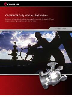
9 The lower master Valve will normally be manually operated, while the upper master Valve is often hydraulicallyactuated. Hydraulic tree wing valves are usually built to be fail safe closed, meaning they require active hydraulic pressure to stay open. Theright hand Valve is often called the flow wing Valve or the production wing Valve , because it is in the flow path the hydrocarbons take to productionfacilities. The left hand Valve is often called the kill wing Valve . It is primarily used for injection of fluids such as corrosion inhibitors or methanol to prevent hydrateformation. The Valve at the top is called the swab Valve and lies in the path used for well interventions like wirelineand coiled tubing. A Choke is a device, either stationary or adjustable, used to control the gas flow, also known as volume, or create downstream pressure, also known as back pressure23 Cameron Multiple Orifice Choke valvesCameron Multiple Orifice Choke valves Cameron s Multiple Orifice valves (MOVs) together with four special trim designs incorporate materials to meet the tough conditions including cavitation, erosion, and freezing, three of the greatest threats to efficient flow control operations.
10 Cameron has an extensive database and can select the proper materials and alloys for specific Choke applications. Continuing investigations to determine the relative erosion, abrasion, and cavitation resistance characteristic of materials allows Cameron to develop improved Choke technologies for enhanced durability and wear resistance. The effects of abrasion, erosion, and cavitation can be reduced by applying hard facing to the interior surfaces of the Choke outlet or by using an extended wear sleeve in the outlet. Specific grades of tungsten carbide are effective at reducing erosion wear, while StelliteTMis most resistant to the destructive consequences of MOV special designs for each applicationThe purpose of the MOV is to provide accurate, calibrated flow control and increased Choke service life in all applications, including erosive conditions.
