Transcription of High Voltage Direct Current Electricity – technical ...
1 IntroductionHigh Voltage Direct Current (HVDC) technology is one of the technical options National Grid can consider for the future development of the transmission system in Great HVDC has some disadvantages, as its integration within an AC system has to be carefully considered and its cost can be higher than the equivalent AC solution, the advantages of HVDC transmission are principally the following: n the ability to interconnect networks that are asynchronous or that operate at different frequenciesn the ability to transmit power over long distances without technical limitationsn the ability to control power flows on the HVDC connection for all system backgroundsn the ability to transmit power in either direction as desired by the network operatorn in certain cases the ability to improve AC system document provides a technical overview of HVDC technology and the situations in which it is applied as an alternative to alternating Current (AC) transmission.
2 It describes the various types of HVDC technology and the components that make up a HVDC connection. It also considers operation and maintenance issues and the costs associated with HVDC Grid owns the high Voltage Electricity transmission system in England and Wales and operates the system throughout Great Britain at 275,000 and 400,000 volts (275kV and 400kV). The National Grid system is made up of approximately 7,200 kilometres (4,470 miles) of overhead line, 1,400 kilometres (870 miles) of underground cable and around 330 Grid has a statutory obligation under the Electricity Act 1989 to develop and maintain an efficient, coordinated and economical system of Electricity transmission, and to facilitate competition in the supply and generation of Electricity . National Grid also has a statutory obligation to have regard to the preservation of amenity in developing the transmission system.
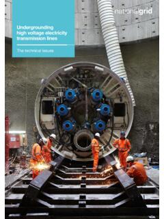
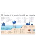
3 FactsheetHigh Voltage Direct Current Electricity technical informationElectric power is normally generated, transmitted and distributed as alternating Current (AC). : CRFS09/08/13 Electric power is normally generated, transmitted and distributed as alternating Current (AC). AC power is well suited to efficient transmission and distribution, as the Voltage can be increased or reduced by transformers. HVDC transmission of Electricity offers some advantages over conventional AC transmission that leads to its selection in particular applications. A typical application of HVDC is to transmit power between two independent AC networks that are not synchronised. Examples of this are the 2,000MW England France interconnector linking the British and French transmission systems and the 1,000MW BritNed interconnector between Britain and The Netherlands. Unlike AC, there is no technical limit on the length of cable or overhead line that can be used in HVDC connections, so HVDC has advantages for long transmission how it worksA typical HVDC system is shown in simplified form in Figure 1.
4 A converter at the sending terminal acts as a rectifier and converts the AC power into DC. A converter at the receiving terminal acts as an inverter and converts the DC power into AC. The connection between the converters may be by overhead line, cable, or both. Power electronic valves (essentially high powered, electronic switches) within the converters allow the power flow to be controlled. The HVDC system is usually designed so that the converter at either terminal can be operated as either a rectifier or inverter and so the direction of the power flow can be reversed as required. Two main converter technologies have been developed, Current source converter (CSC) and Voltage source converter (VSC). HVDC converter technologies Current source converters Current source converters have been in commercial use since the 1950s. Most HVDC systems now in service are of the CSC type and the technology is well established.
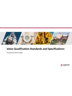
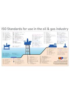
5 A typical Current source converter (CSC) electrical diagram is shown below in Figure 2. As a consequence of the AC-DC conversion technique utilised in CSC technology, the converter absorbs reactive power from the surrounding AC network and generates harmonic currents, both of which impact on the quality of electrical power. AC harmonic filters and reactive compensation must therefore be provided to maintain the quality of the electrical power. A further consequence is that the converter is dependent on the AC system Voltage for its correct operation. The Current flow in the DC circuit is unidirectional. In order to reverse the power flow on a CSC HVDC connection, it is necessary to reverse the polarity of the DC Voltage . This is performed by the DC converter control system. AC harmonic filters are used both to limit AC harmonic currents and to compensate the reactive power absorption of the converter.
6 The filters are switched in and out automatically as required to meet harmonic and reactive power performance limits. Unlike AC, there is no technical limit on the length of cable or overhead line that can be used in HVDC connections, so HVDC has advantages for long transmission distances.~~==+-retrevnoCretrevnoCACsyst emACsystemDC connectionFigure 1: HVDC systemDC SystemAC SystemDC reactorDC filterfiltersPole 1 Pole 2 MetallicreturnconductorYYYYYYV alveConvertertransformerFigure 2: Example Current source converter (CSC) the DC side of the converter, a reactor is provided to smooth the DC Current . The reactor also reduces the peak Current in the event of a fault on the DC connection. DC filters may also be required to reduce harmonic voltages on the DC circuit, particularly when the circuit includes overhead lines. CSC HVDC systems are suitable for operation at high voltages and power transfers.
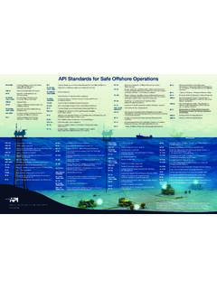
7 A 6,400MW connection between Xiangjiaba and Shanghai in China, operating at +/- 800kV, went into service in 2010. This connection is made via DC overhead lines which are capable of carrying these high Voltage DC currents. Power capabilities via DC cables are presently still limited to lower voltages and power transfer source convertersVoltage source converters (VSC) have been used in HVDC transmission systems since 1997. Comparatively few VSC HVDC systems are in service and the technology is still developing in terms of rating and capability. A typical Voltage source converter is shown in Figure converters use insulated gate bipolar transistor (IGBT) valves. The device is self commutating, meaning that the converter is not dependent on the AC system Voltage for its correct VSC HVDC systems in service so far have been limited to lower voltages and power ratings than CSC systems.
8 The 500MW East-West interconnector between Ireland and Great Britain, operating at +/- 200kV, represented the highest power rating for a VSC HVDC system when it went into service in 2012. Comparison of CSC and VSCThe features of Current source and Voltage source converters are compared in Table source converterVoltage source converterMaturity of technologyMatureDevelopingValvesThyristo r, dependenton AC system voltagefor commutationIGBT, self commutatingCommutation failureCan occurDoes not occurMinimum DC powerTypically 5 10% ofrated powerNo minimum valueReactive powerexchange with ACsystem50% of active powertransmittedIndependent control of active and reactivepowerReactivecompensationRequire dNot requiredAC harmonic filtersSwitchable filtersrequiredLess filtering required, filters need not be switchableConverter transformersSpecial designrequiredConventionaltransformers can beusedReversal of power flowDC Voltage polarityreversal requiredControllable in bothdirections, no reversal of DC Voltage polarity requiredConverter stationfootprint (relative size)
9 200m x 120m x 22m (100%)120m x 60m x 22m(~40%)Conversion losses(per converter end) to oftransmitted power1% oftransmitted powerDC voltageUp to 800kV availableUp to 350kV availableHVDC transmission technologiesCable typesThere are two main types of cable technology suitable for use in HVDC applications, crosslinked polyethylene (XLPE) and mass impregnated (MI) insulation (see Figures 4 and 5). All cables consist of a copper or aluminium conductor surrounded by a layer of insulation (the thickness of which is dependent upon the operational Voltage ), a metallic sheath to protect the cable and prevent moisture ingress and a plastic outer coating. An additional requirement for cables intended for subsea use is steel armouring, which consists of steel wires helically wound around the cable, increasing the cable s strength and protecting it from the rigours of subsea SystemAC SystemConnection tomain ACsystemInterfacetransformerDCcapacitorP hasereactorValveAC filterFigure 3: Example Voltage source converter (VSC)Table 1: Comparison between Current source converter and Voltage source converter 4: MI cableSource: Prysmian Cables & Systems LtdFigure 5: XLPE insulation is made by extruding the polymer over the cable core, and is the technology now generally used for AC transmission cables.
10 XLPE cables are available for HVDC voltages up to 320kV, this could however increase in the future due to advancements in technology. XLPE cables are unsuitable for use in CSC applications where, in order to reverse the direction of power flow, the polarity must be insulation is made by winding kraft paper around the conductor until the required insulation thickness is achieved. The cable is then placed in a vacuum chamber and heated to remove any air and moisture. A viscous oil is introduced which impregnates the paper, increasing the electrical strength of the insulation. A recent development uses polypropylene laminated papers, where thin layers of plastic are laminated to the paper layers, allowing the cable to operate at higher temperatures and therefore higher Current ratings. HVDC, MI cables are presently available for voltages up to installationsGenerally, at least two cables are required for HVDC underground/ subsea transmission, unless an earth/sea electrode is to be used at the converter stations, although it should be recognised there can be environmental issues with such a solution.