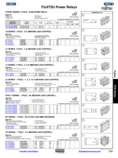
Transcription of Clock Tree 101 - Mouser Electronics
1 By Linda LuaClock tree 1012 Table of is a Clock tree ? tree and tree tree TerminologyWhat is a Clock tree ?A Clock tree is a Clock distribution network within a system or hardware design. It includes the clocking circuitry and devices from Clock source to destination. The complexity of the Clock tree and the number of clocking components used depends on the hardware design. Since systems can have several ICs with different Clock performance requirements and frequencies, a Clock tree refers to the various clocks feeding those ICs. It s often the case that a single reference Clock will be cascaded and synthesized into many different output clocks, resulting in a diagram that looks a bit like a sideways tree trunk. The trunk is the reference Clock and the branches are the various output clocks. Example Clock tree Crystals and XOsClock GeneratorsClock BuffersJitter AttenuatorsTiming ComponentsClock trees can be both very complex with many timing components or very simple with a single reference and a few copies.
2 Of course, their complexity depends on the system they support. While there are many timing component types for many different types of applications, the most common timing components are: -Crystals a piece of quartz or other material that resonates in a predictable pattern at a given frequency when used in conjunction with an on-chip voltage oscillator circuit; -Crystal Oscillators (XOs) a self-contained resonator and oscillator that outputs a given frequency and format;-Voltage controlled oscillators (VCXOs) a self-contained oscillator that varies its output frequency in concert with differing voltages from a voltage reference;- Clock Generators an integrated circuit that uses a reference Clock or crystal to generate multiple output clocks at one or multiple frequencies; - Clock Buffers an integrated circuit that creates copies or derivatives of a reference Clock ; -Jitter Attenuators or Jitter Cleaners an integrated circuit that removes jitter (noise) from a reference and XOsClock GeneratorsClock BuffersJitter AttenuatorsCrystals and Crystal OscillatorsCrystalsingle-ended sine wave outputLVCMOS XOsingle-ended square wave outputDifferential XO differential or complementary square wave outputThree common types of frequency reference sourcesCrystals use quartz, cut at a particular angle and mounted in a protective metal casing, to provide a frequency output when an electrical signal is applied.
3 The output is a single -ended sine wave typically ranging from 32 kHz to 50 MHz. Each output frequency requires a different quartz cut. Crystals require an oscillator circuit to operate. This is generally integrated in the target IC. Crystal Oscillators (XOs) Crystal Oscillators (XOs) integrate the crystal with the oscillator circuit, enabling XOs to provide higher frequency outputs. XOs generate a square wave output that is either single -ended or differential. Differential signaling is used in high-speed, jitter sensitive applications. Some specialized XOs provide multi-frequency support either via I2C or pin control. Crystals and XOs are generally very cost effective unless the application requires a variety of Clock frequencies. Crystals and XOs are typically used as individual IC reference and XOs are generally very cost effective unless the output requirements are stringent. They are typically used as individual IC reference Crystals and XOsClock GeneratorsClock BuffersJitter AttenuatorsClock GeneratorsClock generators are integrated circuits (ICs) that generate multiple output frequencies from a single input reference frequency.
4 The reference frequency may be supplied by a crystal, XO or other Clock that may already be present. Clock generators may also have other features including the ability to turn on/off outputs, skew frequencies, and add spread spectrum to frequencies. They allow feature control through I2C, SPI or pin Clock generator shown below is programmable with up to eight single -ended outputs or four differential outputs. It allows designers to replace eight single -ended crystals or four differential ones. The perceived challenge with Clock generators is in the system layout design. Placing a crystal right next to a target IC is simple and cheap. Routing a signal from a Clock generator might not be. There are many points of view, but generally speaking, systems requiring four or more clocks can economically use a Clock generator. Differential signaling, skew control, careful transmission line design, and other techniques can be used to ensure that a centralized Clock source provides similar performance as multiple discrete Jitter PLLC rystalorRef clockPin or I2 CSilicon Labs Any-Frequency Clock GeneratorOutput ClocksMulti Synth Multi Synth Multi Synth Multi Synth Multi-Format DriversSilicon Labs Si5338 Clock GeneratorCrystals and XOsClock GeneratorsClock BuffersJitter AttenuatorsClock BuffersClock buffers are fairly straight-forward ICs for distributing multiple copies of a Clock to multiple ICs with the same frequency requirements.
5 A buffer s reference Clock can be from a Clock generator, an XO or a Clock already present. Clock buffers scale from 2 outputs to more than 10 they are ICs with integrated logic, Clock buffers can include functions such as signal level format translation, voltage level translation, multiplexing and input frequency division. These features save board space and cost by eliminating additional timing components, external voltage dividers or signal level transition Labs Si5330x Universal BufferPinSilicon Labs Universal Clock BufferOutput ClocksInput ClocksBank ABank BDIVDIVM ulti-Format DriversCrystals and XOsClock GeneratorsClock BuffersJitter AttenuatorsJitter AttenuatorsJitter attenuators are Clock generators with specialized circuitry for reducing jitter. They can also be called Clock cleaners or jitter cleaners. These highly specialized timing devices remove jitter from incoming reference clocks and minimize jitter in the end application.
6 Jitter attenuators are typically used in high-speed applications such as Synchronous Ethernet and SDI Video to ensure that all physical layer data transmission is synchronizedDSPLLINXTALPin or I2C/SPIS iliconLabsSi5345 CLK0 CLK9 NVMINM ultiSynthMultiSynth/INT/INTFB_INOSCS tatus ControlSilicon Labs Si5345 Jitter AttenuatingClockClock vs CrystalFree-Running vs SynchronousClock JitterSelection CriteriaClock tree JitterCrystal, XO or Clock Generator?When to Use a Crystal vs a Clock When starting a Clock tree design, the first step is to inventory all the required Clock frequencies, types, and target IC locations on the system board. Quartz crystals are typically used if the IC has an integrated oscillator and on-chip phase-locked loops (PLLs) for internal timing. Crystals are cost-effective components that exhibit excellent phase noise and are widely available. They can also be placed in close proximity to the IC, simplifying board layout.
7 One of the drawbacks of crystals is that their frequency can vary significantly over temperature, exceeding the parts-per-million (ppm) stability requirements of some applications. In many stability-sensitive high-speed applications, crystal oscillators (XOs) are a better fit because they guarantee tighter temperature stability. Use Clock generators and Clock buffers when several reference frequencies are required and the target ICs are all on the same board or in the same IC or FPGA. In some applications, FPGA/ASICs have multiple time domains for the data path, control plane and memory controller interface and require multiple unique reference frequencies. This is a good place for a Clock generator. A Clock generator or buffer is also better when the IC cannot accommodate a crystal input, when the IC must be synchronized to an external reference (source-synchronous application), or when a high-frequency reference is vs CrystalFree-Running vs SynchronousClock JitterSelection CriteriaClock tree JitterFree Running vs.
8 Synchronous?Free-Running versus Synchronous Clock Trees (Part 1)Once the Clock inventory has been completed, the next step is to determine and comply with the required timing architecture: free-running or synchronous? Free running applications require one or more independent clocks without any special phase-lock or synchronization requirements. Example applications are standard processors, memory controllers, SoCs and peripheral components ( , USB and PCI Express switches). Free-Running Clock tree ExamplesClock vs CrystalFree-Running vs SynchronousClock JitterSelection CriteriaClock tree JitterFree-Running versus Synchronous Clock Trees (Part 2)Synchronous applications require continuous communication and network-level synchronization. Examples are Optical Transport Networking (OTN), SONET/SDH, mobile backhaul, synchronous Ethernet and HD SDI video transmission. These applications require transmitters and receivers to operate at the same frequency.
9 Synchronizing all SerDes (serialization-deserialization) reference clocks to a highly accurate network reference Clock ( , Stratum 3 or GPS) guarantees synchronization across all nodes. In these applications, low-bandwidth PLL-based clocks provide jitter filtering to ensure that network-level synchronization is maintained. Networking line card PLL applications generally use specialized jitter attenuating clocks or discrete PLLs with voltage-controlled oscillators. For optimal performance, a jitter attenuating Clock should be placed at the end of the Clock tree , directly driving the SerDes device. Clock generators and buffers can be used to provide other system Clock tree ExampleFree Running vs. Synchronous? Clock vs CrystalFree-Running vs SynchronousClock JitterSelection CriteriaClock tree JitterClock Jitter What Is It? Clock jitter is a critical specification for timing components because excessive Clock jitter compromises system performance.
10 There are three common types of Clock jitter, and depending on the application, one type of jitter will be more important than another. Cycle-to-cycle jitter measures the maximum changein the Clock periodbetween any two adjacent Clock cycles, typically measured over 1,000 cycles. Period jitter is the maximum deviation in Clock period with respect to an idealperiod over a large number of cycles (10,000 is typical). Phase jitter is the figure of merit for demanding, high-speed SerDesapplications. It is a ratio of noise power to signal power calculated by integratingthe Clock single sideband phase noise across a range of frequencies offset froma carrier Labs provides a detailed investigation of timing jitter in the Timing Jitter Dictionary and Technical Guide available at the button below. Timing Jitter Dictionary & Technical GuideClock vs CrystalFree-Running vs SynchronousClock JitterSelection CriteriaClock tree JitterSelecting ComponentsIt is important to evaluate devices based on maximum (MAX) jitter performance.