Transcription of Code Compliant Construction
1 Code Compliant Construction of Conventionally Framed Roofs and Roof TrussesOverviewIntroduction This presentation covers the requirements for conventionally framed roofs and roof truss Construction per International Residential Code (IRC) Section The code allows portions of a structure to be engineered in accordance with the International Building Code (IBC), without the entire structure requiring engineering. ( ) This means that some portions of the building may be engineered ( trusses and other components), but the structure may still be able to utilize IRC prescriptive requirements. Applications Structures within the scope of prescriptive code compliance include: Detached one-and two-family dwellings and townhouses with separate means of egress [ ] Light- frame Construction (platform or balloon frame ) [ ]Prescriptive Code Compliance The following three tables list additional criteria the structure must meet with respect to loads and geometry:Prescriptive Code Compliance -LoadsLoadMaximum AllowedCode SectionRoof Live20 Live10, 20, 30 or 40 Speed (2012)110 (4)AWind Speed (2006/9)110 mph100 mph hurricane-prone TownhousesSDC: C, D0, D1, & (SDC: A & B exempt)Seismic 1-& 2-familySDC: D0, D1, & (SDC.)
2 A, B & C exempt)Prescriptive Code Compliance -Structure GeometryDescriptionMaximum AllowedCode SectionStory Height10' (laterally unsupported) plus floor framing not to exceed 16" or 12' as allowed by (5)Number of Stories3 above grade Width (perpendicular to ridge)36'footnote to Tables (1) & (2)]Building Length (parallel to ridge)Not specified for wood[CFS & ICF limited to 60']Mean Roof HeightUp to 60' with application of adjustment factorsTable (1), Table (1) & Section Code Compliance -Roof GeometryDescriptionMaximum AllowedCode SectionBuilding Width (perpendicular to ridge)40' (36' building plus max 24" overhang each side)footnote to Tables (1) & (2) & SpanMaximum tabulated or 26'Footnote b Table (1)-(8)Ceiling Joist SpanMaximum tabulated or 26'Footnote b Table (1) & (2)Rafter/Ceiling Joist Spacing24" (1)-(8) & Table (1) & (2)Roof Pitch3/12 to 12/12 or greaterTable & Code Compliance Finally, and perhaps most importantly, to meet prescriptive code compliance: Construction documents shall be of sufficient clarity to indicate the location, nature and extent of work and show in detail that such work conforms to the provisions of the code [ ].
3 A complete load path from peak of roof to the foundation is required [ ].What is a Load Path? A complete load all requirements for transfer of all loads from their point of origin through the load-resisting elements to the foundation. ( )What is a Load Path? While framers build from the bottom up, load paths must be traced from the top down. Loads are typically applied on the roof surface and travel down to the foundation. In between roof and foundation, loads must be transferred along elements that are adequate to carry these is a Load Path? Loads and load directions Vertical loads Gravity easiest to trace from roof to foundation Uplift less well understood Lateral loads Parallel and perpendicular to structural element Wind, Seismic most difficult to address adequatelyVerticalLoads(gravity anduplift)LateralLoads(perpendicularto wall)LateralLoads(parallelto wall)Lateral Loadapplied to end wallLateral Loadapplied to side wallConventional Framing Problem Areas Conventional roof framing and compliance with code requirements, including those involving the load path, is a complex topic.
4 Conventional Framing Requirements The IRC covers many roof framing elements in the prescriptive requirements: Gable/Shed Hip/Valley Roof Openings Notches and HolesConventional Framing Requirements However, the IRC gives no guidance on other aspects of the roof framing, such as: Bracing design for high end of hip/valley rafters Bracing design for rafter purlins Non-symmetrical hip roofs Roof diaphragms with plate height changes Large roof openings (greater than 6' wide)Conventional Framing Problem Areas A clear understanding of all framing code requirements is essential to avoid many pitfalls, as shown in the following : Aries EngineeringExample: Load Path (Roof Dormer) The main ceiling joists are supported by a girder that is supported on next to nothing. The joists should run further into the dormer, and the girder supporting them should be supported by posts in the dormer side : Load Path (Roof Dormer) The load path from the dormer flows down the side wall.
5 However, the side wall does not extend to the floor in this area. The load path needs to flow into the rafter next to the dormer side wall. However, only a single rafter is placed here. If this rafter is supporting the dormer roof, it should designed to carry the : Load Path (Roof Dormer) If this had been designed with trusses, a tail bearing girder truss designed to carry this load would have been used : Load Path (Wall) Whether using conventional framing or trusses, it is essential to pay attention to load paths, especially with today s larger, more complex : Load Path (Wall) Where girder trusses are needed, large concentrated loads on exterior wallscan : Load Path (Wall) Doubled I-joists in a roof-ceiling assembly carry a significant load, but they bear on two top plates between studs. Note the joint in the lower of the two top plates. Joints in plates need not occur over studs; however, this is a particularly bad place for one. Similarly, a 4-ply beam bearing on the wall at right has no studs under it to transfer the load to the floor : Load Path (Wall) For tall walls (over 10 in height) both gravity and lateral load paths need to be considered and are more complicated and critical.
6 Any break in the continuity of these studs creates a hinge in the wall, which can easily deform or fail under wind load : Load Path (Wall) Not only is there a hinge created in this case but the outward thrust of the rafters also needs to be resisted. It is not clear in the previous picture how this is being : Load Path (Floor) In truss Construction , loads are typically carried by the outside walls and transferred down to the foundation walls. With conventional frame Construction , loads must be transferred through the interior of the structure. Example: Load Path (Floor) This can lead to large concentrated loads transferred through interior walls. Loads cannot be terminated on or, even worse, between floor framing elements without specific engineering : Load Path (Floor) In this house plan, very few framing elements stack from level to level. The loads shown are approximate and reflect a 20 psflive or snow load and a 10 psf dead load. Loads will vary depending on snow load and details of the framing.
7 Example: Load Path (Floor) With few walls stacking or crossing, very few points exist to take roof loads down to the foundation. The stack points that do exist are not in useful Framing Problem Areas Additional areas to watch closely: Connections Supports Structural member sizingExample: Connection (Floor Sag) In this example, you can see a post at a corner of an interior wall. It is carrying a significant load from the beam above. Example: Connection (Floor Sag) In the photo on the right, you can see this post rests on two different bottom plates and the floor appears to be sagging. This is a case where the roof loads applied to the floors were not considered thus the : Connection (Floor Sag) In this photo, we can see a fairly clear sag in the floor at this post in a wall. This demonstrates that, if the path for these loads is not considered all the way down to a foundation element, there can easily be deflection problems, or low points in floors and possibly failure.
8 Again, in this case the roof loads applied to the floors were not considered thus the sag. Example: Connection (Power Blocking) The IRC includes fastener requirements for conventional Construction within the scope of the code. Problems may arise where there is end-grain nailing or where multiple members are joined. For example, nailing details like the one at right may or may not be sufficient, depending on : Connection (Power Blocking) Power Blocking is not addressed or approved by the building code. In some cases, engineered design may be required. With trusses, much shorter end jacks are made to have a mechanical connection. Even where the code does cover a specific situation, it is often difficult to inspect whether the fasteners used meet : Connection (Roofs) A basic problem of inspecting nailed connections is knowing whether the nails meet the code s fastener schedules. IRC Table (1) addresses a number of roof framing itemsExample: Connection (Roof Diaphragm) The heel connection at right was made in the plant, avoiding the difficulty of correctly connecting rafters to joists as in conventional Construction .
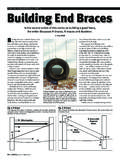
9 With trusses, the overall flow of loads is well defined, so specific mechanical fasteners can be utilized to meet resistance needs. Example: Connection (Hip Rafters) This connection is probably not adequate. Trying to attach 5 members to the end of the ridge would require so many nails it would cause splitting in the ridge. End and edge distance limits on proper nailing would be violated. This joint as built is also weakened by the gap between these two : Connection (Hip Rafters) With structural building components, connections where multiple members are joined are typically made with engineered mechanical fasteners. Example: Support (Bearing) Inadequate bearing supports are another problem in conventional Construction . A structural bearing element must carry a structural member s gravity or uplift loads to the foundation. The bearing element must also be able to carry any concentrated or lateral loads parallel or perpendicular to the bearing : Support (Bearing) braces often connect to the top edge of LVL or conventional lumber beams.
10 Beam span tables are typically not accurate when braces are used because the tables assume: Uniform loads only, while the braces apply concentrated loads to the beam Full top edge support is present (to prevent torsional buckling) The top edge of the LVL at right is not braced. In fact, the braces supporting the purlin run into the LVL at an angle, increasing buckling forces on : Support (Rafter) This is an example of inadequate support of a valley rafter bearing on an unsupported : Support (Rafter) The photo on the right shows the end of a ridge beam for a dormer bearing on a 2x4. These problems of structural support in conventionally framed roofs tend to appear more often in complex and large roofs. Example: Support (Rafter) The design of roofs of almost any complexity or size, however, can be accommodated fairly simply with trusses. The Truss Placement Diagram shows how these are laid out, and there is no guesswork on the jobsite about how the roof is to be adequately structurally supported.