Transcription of DESIGN - WoodWorks
1 The Wood Products Council is a Registered Provider with . Credit(s) earned on completion of this program will be reported to AIA/CES for AIA members. Certificates of Completion for both AIA members and non-AIA members are available upon request. This program is registered with AIA/CES for continuing professional education. As such, it does not include content that may be deemed or construed to be an approval or endorsement by the AIA of any material of construction or any method or manner of handling, using, distributing, or dealing in any material or product.
2 Questions related to specific materials, methods, and services will be addressed at the conclusion of this presentation. Copyright Materials This presentation is protected by US and International Copyright laws. Reproduction, distribution, display and use of the presentation without written permission of the speaker is prohibited. The Wood Products Council 2012 Learning Objectives At the end of this program, participants will be able to: the versatility of and range of applications for post frame (PF) building systems the structural features that make PF building systems unique the available resources for DESIGN of PF building systems key performance characteristics of PF building systems the two primary post frame construction systems INTRODUCTION TO post frame CONSTRUCTION, BUILDINGS & DESIGN Presentation prepared by Harvey B.
3 Manbeck, , PhD Professor Emeritus Penn State University Research & Technical Advisor National frame Building Association (NFBA) 1. Identify the versatility of and range of applications for post frame (PF) building systems 2. Identify the structural features that make PF building systems unique 3. Identify the available resources for DESIGN of PF building systems 4. Identify key performance characteristics of PF building systems 5. Identify the two primary post frame construction systems LEARNING OBJECTIVES At the end of this program, participants will be able to: WHAT IS PF BUILDING USED FOR?
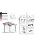
4 RESTAURANT AND RETAIL CHURCHES COMMUNITY BUILDINGS MUNICIPAL BUILDINGS RESIDENTIAL AGRICULTURAL AND HORSE FACILITIES Continuous Footing or Pier Foundation post Pinned Connection Girder (Beam) Concrete Pier Floor post -AND-BEAM CONSTRUCTION ELEVATION post -AND-BEAM CONSTRUCTION PLAN VIEW post Girder (Beam) Purlin PF BUILDING SYSTEM PICTORIAL VIEW Alternative post Foundations Purlins Wood Columns Wall Girts Sheathing Truss PF BUILDING SYSTEM PLAN VIEW Purlin post Girder (Header) Clear Span Truss PF BUILDING SYSTEM CROSS SECTION X-section Purlins Truss Girts Splashboard Eave Height Clear Span post Height post Foundation post Footing Sidewall post Wood sidewall posts Wide bay ( post ) spacing 8 ft and greater Large clear spans More than 100 ft Embedded wood post or concrete piers serve as building foundation Attached wall and roof sheathing/cladding form structural shear wall/structural diaphragm system for lateral loads PF BUILDING SYSTEM FEATURES Usually wood posts Either solid-sawn, glue-laminated (glulam)
5 Or mechanically (nail) laminated Typically nominal 6-x-6, 6-x-8, 8-x-8, or 8-x-10 cross section Usually spaced 4, 6, 8, 12 or 16 ft on center along sidewall Portion of post embedded into ground (plus 6 12 in. above ground) is preservative treated WOOD SIDEWALL POSTS Spliced glulam post 3 or 4 ply, fabricated with 2x lumber lower portion preservative treated; upper portion untreated GLUE-LAMINATED (GLULAM) WOOD post Preservative-treated section spliced to untreated portion NAIL-LAMINATED POSTS Treated NAIL-LAMINATED POSTS Nail-laminated posts with treated bottom spliced to untreated top Preservative-treated splash board Nail-laminated posts attached to precast concrete pier foundation above ground line HYBRID post OPTIONS Concrete Pier Untreated post PRESSURE-PRESERVATIVE TREATMENTS For posts embedded in ground, specify use category UC4B or better per AWPA-U1-XX ( , pcf)
6 post FOUNDATION OPTIONS Pressure Preservative post Embedded Directly into Ground to 5 ft embedments typical A shallow post foundation post FOUNDATION OPTIONS EMBEDDED TREATED post Embedment provides lateral and vertical support for bldg Typically embedded 5 ft depth Bottom concrete collar or wood cleat improves uplift resistance of post post hole is typically 24 30 in diameter; back-filled with well graded gravel, sand, or excavated soil PRECAST REINFORCED CONCRETE PIER Precast reinforced concrete pier with post attached above grade Entire assembly pre-engineered Assembly usually fabricated in factory and shipped to site as a single unit PRECAST REINFORCED CONCRETE PIER Connection details for a typical precast reinforced-concrete post foundation Cleat Reinforcement CAST-IN-PLACE CONCRETE FOUNDATION WALL post attached to 6 in.
7 Or wider cast-in-place concrete foundation wall Solid-sawn, nail-laminated, or glulam posts attached to top of foundation wall 18 24 in. above grade and are usually untreated Connection Hardware Untreated post THICKENED CONCRETE SLAB post set on thickened edge of a concrete floor slab Thickened portion of slab reinforced post typically untreated THICKENED CONCRETE SLAB Blow-molded plastic barriers, HDPE barriers, asphalt based wraps Provides moisture and insect protection Enhances protection of copper-based, chemical-treated wood posts or laminated columns PROTECTIVE post COVERS Pre-engineered metal plate connected 2x lumber trusses typically spaced 4 8 ft on center sometimes double trusses used on wider clear spans Heavier timber (solid-sawn wood or glulam) trusses for larger post and truss spacings Solid-sawn wood rafters spaced 2 4 ft on center for shorter clear spans Glulam or structural composite lumber (SCL)
8 Rafters for larger rafter spacings or clear spans ROOF FRAMING Setting pre-engineered wood trusses for a typical PF building ROOF FRAMING Trusses Sidewall post Connected Directly to Trusses Posts are connected directly to the roof framing if post and roof-framing spacing are the same Posts and roof framing are often connected to header beams if post and roof-framing spacing are not the same post -TO-ROOF FRAMING CONNECTIONS Typical for a nail-laminated post -to-truss connection Connection is usually a pinned connection NAIL-LAMINATED post CONNECTIONS Block Height Block NAIL-LAMINATED post CONNECTIONS post -to-truss connection for a nail-laminated post application NAIL-LAMINATED post CONNECTIONS post -to-truss connection for a nail-laminated post application SOLID-SAWN post CONNECTIONS Typical post -to-truss connection details for a solid-sawn post application 1 Connection with truss fastened to side of post and with bearing block Connection with truss bearing on notch in post post -TO-ROOF FRAMING CONNECTION Schematic of typical connection details Truss to header (girder) Header (girder)
9 To roof truss HEADER CONNECTIONS Typical roof framing to header connection detail with blocking placed between parallel header beams (girder) Metal Plate Connector Header (Girder) Blocking ROOF PURLIN PLACEMENT Purlins placed either on top or inset between truss top chords or inset between roof rafters Purlins oriented flat or on-edge depending upon truss and purlin spacing ROOF FRAMING AND PURLINS Typical PF system showing pre-engineered roof trusses attached to post and roof purlins attached to top of the truss chords Truss Purlin Truss to post Connection 8 ft 2 ft Typically 2-x-4 to 2-x-8 solid-sawn lumber spaced 24 32 in.
10 Apart Placement and orientation Oriented flat on outside face of wall post (for smaller post and girt spacings and loads) OR Oriented on-edge between adjacent posts (for larger loads and/or post or girt spacings) WALL GIRTS Typical wall girt and metal sheathing application to PF building system WALL GIRTS AND SHEATHING Wall Girt Sheathing PF system with wall girts and wood structural panel sheathing attached WALL GIRTS AND SHEATHING Corner bracing in upper chords of trusses Diagonal bracing for lower chords of trusses Lower chord stiffeners for trusses X-bracing of selected compression webs Continuous longitudinal bracing of long-compression webs and chords of trusses or T-bracing for long compression webs ROOF TRUSS AND LATERAL WIND BRACING Guide to Good