Transcription of Coiled Tubing Hydraulics Modeling - NOV
1 Tech NoteCTES, , Pozos LaneConroe, Texas 77303phone: (936) 521-2200fax: (936) Tubing Hydraulics ModelingSubject Matter Authority: Bharath RaoMay 10, 1999 SummaryThis document presents a general formulation of the governing equation used to determine the system pressure losses for liquids, gases, and mul-tiphase fluids. Both CT and annulus flow are ..2CT and Annular Flow ..4 Annular Flow ..6 Pressure Losses in Liquids ..6 Newtonian Plastic Model ..11 Pressure Losses in Gases ..12 Pressure Losses in Losses in Multiphase Fluids ..15 Duns and Ros Correlation ..17 Hagedorn and Brown Correlation.
2 19 Orkiszewski Correlation ..19 Beggs and Brill Correlation ..21 General ..23 Greek Symbols ..24 Subscripts ..25 Superscripts ..25 References ..25 Coiled Tubing Hydraulics ModelingTech NoteCTES, most Coiled Tubing (CT) applications such as cleanouts, well unloading, acidizing, stimulation, drilling, etc., fluid (liquid, gas, or multiphase mix-ture of liquid and gas) is pumped through the CT to a desired depth in the wellbore, and returned up the annulus. The fluid returning in the annulus that is formed between the CT and production Tubing /casing can be a mul-tiphase mixture of the pumped CT fluid, reservoir fluid, original wellbore fluid, and sand or drilled solid particles, depending on the application.
3 Water, air, nitrogen, diesel, brines, acids, gels, and foams are among the many commonly pumped fluids through CT in various applications. Thus, depending on the fluid type and properties, system pressures (pump pres-sure, gooseneck pressure, wellhead pressure, flowing bottom hole pres-sure) change and affect the pumping requirements. In addition, system pressures are also affected by many other parameters such as pump rate, CT size (length, diameter), reel core diameter, geometry of the wellbore, and surface a fluid mechanics viewpoint, flows that occur during any CT applica-tion can be broadly classified as:!
4 Compressible (fluid density is a strong function of pressure such as in gases) or incompressible (fluid density is a very weak function of pres-sure such as for liquids)!steady (flow is independent of time) or unsteady (flow is time-depen-dent)!laminar (flow is characterized by layers or streamlines) or turbulent (flow is characterized by random mixing and is no longer streamlined)!single-phase ( only one fluid phase exists as either liquid or gas) or mul-tiphase (at least two phases exist as in liquid and gas; or liquid, gas, and solid)!Newtonian (shear stress is linearly related to shear rate) or non-Newto-nian (shear stress is not linearly related to shear rate)!
5 Upwards or downwards in a vertical, inclined, or horizontal wellbore!in the CT or in the annulus formed between the CT and production tub- order to accurately predict the system pressures in any CT operation, all these fluid mechanics aspects and parameters must be taken into careful consideration during the mathematical development of a wellbore hydrau-lics model for CT Tubing Hydraulics ModelingTech NoteCTES, pressures can be estimated by appropriately accounting for the total pressure losses ( P) in the CT and annulus. In general, the total pressure loss is comprised of three components:!
6 Hydrostatic pressure loss ( Ph),!friction pressure loss ( Pf), and!acceleration pressure loss ( Pa).The magnitude of each of these components is largely affected by fluid properties such as density and viscosity, and the total pressure loss can be accurately predicted only if the fluid properties are evaluated correctly. Moreover, the frictional component of the Coiled Tubing pressure loss can be further subdivided into two parts: a part that accounts for the friction pressure loss on the reel ( PCT) before entering the well, and a part that accounts for the straight Tubing losses ( PST) in the well.
7 Experiments [McCann and Islas (1996); Azouz et al. (1998)] have shown that, in gen-eral, Coiled Tubing pressure losses are greater than the corresponding straight Tubing pressure losses, and therefore must be accounted for appro-priately while determining the system pressure document presents a general formulation of the governing equations to determine the system pressure losses for various fluids (liquids, gases, foams, and multiphase fluids). The analysis considers both CT and annulus flow. The evaluation of fluid properties, such as density and viscosity, for each of these fluid types is discussed in detail with an emphasis on the influence on the system pressure losses.
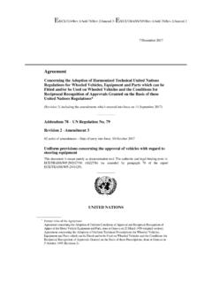
8 In addition, criteria for the onset of turbulence and evaluation of friction factors are discussed for all fluid types considered. Furthermore, correlations that determine the friction fac-tor in reeled Coiled Tubing (fCT) in relation to the friction factor (fST) for straight Tubing are also presented for some fluid Tubing Hydraulics ModelingTech NoteCTES, and Annular FlowCT FlowThe governing equation for system pressure losses stems from the mechan-ical energy balance, and is written for a Coiled Tubing segment as shown in Figure , the total pressure loss ( Ps=P2-P1, where P1 and P2 are the pres-sures at points 1 and 2 respectively)
9 For downward flow through a CT seg-ment of length L inclined at an angle to the vertical is given byEQ 1where the hydrostatic (), frictional (), and acceleration () components can be written asEQ 2EQ 3andEQ 4In Eq 1 through Eq 4, superscript s refers to segment; h is the vertical dis-tance between points 1 and 2 and is given by h=Lcos ; g is the accelera-tion due to gravity; gc is the Newton s law conversion constant for the English system of units; f is the Moody s friction factor; De is the equiva-lent diameter of the conduit (inside diameter of CT); is the mean density FIGURE 1CT segment of length L and inclined at an angle to the verticalflowCT12Lh sasfshsPPPP = shP sfP saP cshgghP = ecsfDgLvfP22 = )(22122vvgPcsa = Coiled Tubing Hydraulics ModelingTech NoteCTES, the fluid between points 1 and 2; v is the mean velocity of the fluid between points 1 and 2; and, v1 and v2 are the fluid velocities at points 1 and 2 respectively.
10 It should be noted for horizontal flow ( = 90 degrees) in the CT, is zero, and only the frictional and acceleration contribu-tions to the pressure loss exist. In addition, Eq 1 through Eq 4 and all sub-sequent equations in this document are written in consistent units unless otherwise friction factor in Eq 3 is a function of the Reynolds number (Re), defined physically as the ratio of the inertia force to the viscous force. Mathematically, the definition of Re varies depending on the fluid type ( , Newtonian liquids, non-Newtonian liquids, gases, multiphase fluids), and therefore will be presented separately for each of the fluid types.