Transcription of Schneider Electric Altivar 312 Programming Manual
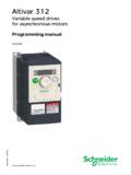
1 BBV46385 11/2008 Altivar 312 Variable speed drivesfor asynchronous motorsProgramming manual06/2010 Courtesy of Steven Engineering, Ryan Way, South San Francisco, CA 94080-6370-Main Office: (650) 588-9200-Outside Local Area: (800) of Steven Engineering, Ryan Way, South San Francisco, CA 94080-6370-Main Office: (650) 588-9200-Outside Local Area: (800) 06/20101 ContentsImportant information _____ 4 Before you begin_____ 5 Documentation structure_____ 7 Software enhancements _____ 8 Steps for setting up the drive _____ 9 Setup - Preliminary Recommendations _____ 10 Factory configuration _____ 11 Basic functions _____ 12 Remote display terminal option, ATV31 _____ 14 Remote graphic display terminal option, ATV61/ATV71_____ 15 Remote display terminal option.
2 ATV12 _____ 19 Structure of the parameter tables _____ 20 Compatibility of functions _____ 21 List of functions that can be assigned to inputs/outputs _____ 23 List of functions that can be assigned to the Network and Modbus control word bits _____ 25 Checklist _____ 26 Programming _____ 27[SPEED REFERENCE] (rEF-) menu _____ 31[SETTINGS] (SEt-) menu _____ 32[MOTOR CONTROL] (drC-) menu _____ 41[INPUTS / OUTPUTS CFG] (I-O-) menu _____ 47[COMMAND] (CtL-) menu_____ 50[COMMAND] (CtL-) menu_____ 61[APPLICATION FUNCT.] (FUn-) menu _____ 62[FAULT MANAGEMENT] (FLt-) menu _____ 91[COMMUNICATION] (COM-) menu _____ 98[MONITORING] (SUP-) menu _____ 100 Migration ATV31 - ATV312_____ 105 Diagnostics and troubleshooting_____ 106 Index of functions _____ 111 Index of parameter codes and customer settings_____ 112 Courtesy of Steven Engineering, Ryan Way, South San Francisco, CA 94080-6370-Main Office: (650) 588-9200-Outside Local Area: (800) 06/2010 Important informationNOTICERead these instructions carefully, and look at the equipment to become familiar with the device before trying to install, operate, or maintainit.
3 The following special messages may appear throughout this documentation or on the equipment to warn of potential hazards or to callattention to information that clarifies or simplifies a NOTEThe word "drive" as used in this Manual refers to the "controller portion" of the adjustable speed drive as defined by equipment should be installed, operated, serviced, and maintained only by qualified personnel. No responsibility is assumed bySchneider Electric for any consequences arising out of the use of this documentation. 2009 Schneider Electric . All rights indicates an imminently hazardous situation which, if not avoided, will result in death, serious injury orequipment damage.
4 WARNINGWARNING indicates a potentially hazardous situation which, if not avoided, can result in death, serious injury orequipment damage. CAUTIONCAUTION indicates a potentially hazardous situation which, if not avoided, can result in injury or equipment , used without the safety alert symbol, indicates a potentially hazardous situation which, if not avoided, canresult in equipment addition of this symbol to a Danger or Warning safety label indicates that an electrical hazard exists, which will result inpersonal injury if the instructions are not is the safety alert symbol. It is used to alert you to potential personal injury hazards.
5 Obey all safety messages that followthis symbol to avoid possible injury or of Steven Engineering, Ryan Way, South San Francisco, CA 94080-6370-Main Office: (650) 588-9200-Outside Local Area: (800) 06/20105 Before you beginRead and understand these instructions before performing any procedure with this OF Electric SHOCK, EXPLOSION, OR ARC FLASH Read and understand this Manual before installing or operating the Altivar 312 drive. Installation, adjustment, repair, andmaintenance must be performed by qualified personnel. The user is responsible for compliance with all international and national electrical code requirements with respect to grounding ofall equipment.
6 Many parts of this drive, including the printed circuit boards, operate at the line voltage. DO NOT TOUCH. Use only electricallyinsulated tools. DO NOT touch unshielded components or terminal strip screw connections with voltage present. DO NOT short across terminals PA/+ and PC/ or across the DC bus capacitors. Before repairing the variable speed drive:- Disconnect all power, including external control power that may be Place a DO NOT TURN ON label on all power Lock all power disconnects in the open WAIT 15 MINUTES to allow the DC bus capacitors to discharge. - Measure the voltage of the DC bus between the PA/+ and PC/ terminals to ensure that the voltage is less than 42 If the DC bus capacitors do not discharge completely, contact your local Schneider Electric representative.
7 Do not repair or operate the drive Install and close all covers before applying power or starting and stopping the to follow these instructions will result in death or serious EQUIPMENT OPERATION Read and understand this Manual before installing or operating the Altivar 312 drive. Any changes made to the parameter settings must be performed by qualified to follow these instructions will result in death or serious injury. WARNINGDAMAGED EQUIPMENTDo not install or operate any drive that appears to follow these instructions can result in death, serious injury, or equipment of Steven Engineering, Ryan Way, South San Francisco, CA 94080-6370-Main Office: (650) 588-9200-Outside Local Area: (800) 06/2010 Before you begina) For additional information, refer to NEMA ICS (latest edition), "Safety Guidelines for the Application, Installation, and Maintenance ofSolid State Control" and to NEMA ICS (latest edition), "Safety Standards for Construction and Guide for Selection, Installation andOperation of Adjustable-Speed Drive Systems".
8 WARNINGLOSS OF CONTROL The designer of any wiring diagram must take account of potential control channel failure modes and, for certain critical controlfunctions, incorporate a way of achieving a safe state during and after a channel failure. Examples of critical control functions areemergency stop and overtravel stop. Separate or redundant control channels must be provided for critical control functions. System control paths may include communication links. Consideration must be given to the implications of unanticipated transmissiondelays or failures of the link. aFailure to follow these instructions can result in death, serious injury, or equipment of Steven Engineering, Ryan Way, South San Francisco, CA 94080-6370-Main Office: (650) 588-9200-Outside Local Area: (800) 06/20107 Documentation structureThe following Altivar 312 technical documents are available on the Schneider Electric website ( ) as well as onthe DVD-ROM (reference VW3A8200).
9 Installation ManualThis Manual describes how to install and connect the manualThis Manual describes the functions and parameters of the drive's terminals and how to use StartThis document describes how to connect and configure the drive so that the motor can be started both quickly and easily for basicapplications. This document is supplied with the for Modbus, CANopen, manuals describe the installation process, the bus or network connections, signaling, diagnostics and the configuration of parametersspecific to also describe the communication services of the of Steven Engineering, Ryan Way, South San Francisco, CA 94080-6370-Main Office: (650) 588-9200-Outside Local Area: (800) 06/2010 Software enhancementsSince it was first marketed, the Altivar ATV 312 has been equipped with additional functions.
10 Software version IE 50 has now beenupdatedto IE 54. This documentation relates to version IE software version appears on the rating plate attached to the side of the made to version IE 54 in comparison to IE 50 New possible configuration - Remote configuration : By pressing the MODE button during 3 seconds, the drive switches automatically to Remote configuration. The embedded Jog Dial works as a potentiometer (Fr1 = AIV1) and embedded RUN button is Local configuration : It is possible to go back to Local configuration by pressing again the MODE button during 3 seconds (see page 28)Courtesy of Steven Engineering, Ryan Way, South San Francisco, CA 94080-6370-Main Office: (650) 588-9200-Outside Local Area: (800) 06/20109 Steps for setting up the drive3.
