Transcription of Common Rail System (HP3) for MITSUBISHI TRITON
1 00400554 ECommon rail System (HP3)for MITSUBISHI TRITON 4D56/4M41 EngineDENSO INTERNATIONAL THAILAND CO., LTD 2005 DENSO CORPORATIONAll Rights Reserved. This book may not be reproducedor copied, in whole or in part, without the writtenpermission of the HistoryRevision HistoryDateRevision Portions of Diagnostic Trouble Code Datails" revised. (See P1-37, 38, 39, 40, 41) " engine ECU Externa Wring Diagram illustration (Applicable Illust. code: Q001257E,Q001258E) replaced. (See P1-42, 43) Portions of the " engine ECU Connector Diagram Terminal Connections (1), (2), (3) replaced.
2 (See P1-43, 44, 45)Table of ContentsOperation Section1. PRODUCT APPILCATION .. Components Part Number .. 1-12. OUTLINE OF rail System Characteristics .. of Injection to the Conventional .. System .. System .. 1-43. SUPPLY View Diagram .. Pump Internal Fuel Flow .. of Supply Pump .. of the Supply 1-94. SUPPLY PUMP COMPONENT Pump .. ( Suction Control Valve ) .. Temperature Sensor .. 1-135. 1-146. rail COMPONENTS Pressure Sensor (Pc Sensor) .. limiter .. 1-157. INJECTOR (G2 TYPE) .. View Diagram .. Codes .. Actuation Circuit .. 1-218. OPERATION OF CONTROL SYS-TEM Control System ECU (Electronic Control Unit).
3 Recognition Sensor (TDC).. Pressure Sensor .. Air Flow Sensor .. Control Throttle .. 1-259. VARIOUS TYPES OF Injection Rate Control Injection Quantity Control Function .. Injection Timing Control Injection Pressure Control Function ( rail Pressure Control Function) .. 1-2710. FUEL INJECTION QUANTITY Injection Quantity Calculation Method .. Set Injection Quantities .. 1-28 Table of Contents11. FUEL INJECTION TIMING Main and Pilot Injection Timing Microinjection Quantity Learning Control .. 1-3312. FUEL INJECTION RATE 1-3513. FUEL INJECTION PRESSURE Fuel Injection Pressure.
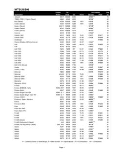
4 1-3614. DIAGNOSTIC TROUBLE CODES (DTC) About the Codes Shown in the Diagnostic Trouble Code 1-3715. EXTERNAL WIRING engine ECU External Wiring Diagram .. engine ECU Connector Diagram .. 1-43 Operation Section1 11. PRODUCT APPILCATION System Components Part NumberVehicle Manufac-tureVehicle NameEngine ModelSpecificationDestination (Vol-ume)Line Off PeriodMITSUBISHITRITON4D562WD (MT/AT)ThailandJune, 20054WD (MT)4M414WD (MT/AT)Parts NameDENSO P/NManufacturer P/NRemarksSupply pumpSM294000-03311460A001 For 4D56 engine ModelSM294000-03411460A003 For 4M41 engine ModelInjectorSM095000-56001465A041 For 4D56 engine ModelSM095000-57601465A054 For 4M41 engine ModelRailSM095440-06401465A034 ALLE ngine ECUMA275800-425#1860A392 For 4D56 engine Model (4WD)MA275800-431#1860A523 For 4D56 engine Model (2WD MT)
5 MA275800-432#1860A524 For 4D56 engine Model (2WD AT)MA275800-357#1860A390 For 4M41 engine Model (4WD)Turbo pressure sensor079800-5960MR577031 ALLC ylinder recognition sensor(TDC)949979-15901865A074 For 4M41 engine ModelElectronic control throttle197920-00201450A033 For 4M41, 4D56 engine Model (4WD)Fuel temperature sensor179730-0020MR547077 ALLMass air flow meterVN197400-40301460A001 ALLO peration Section1 22. OUTLINE OF Common rail System CharacteristicsThe Common rail System uses a type of accumulation chamber called a rail to store pressurized fuel, and injectors that contain elec-tronically controlled solenoid valves to inject the pressurized fuel into the cylinders.
6 Because the engine ECU controls the injectionsystem (injection pressure, injection rate, and injection timing), the injection System is independent, and thus unaffected by the enginespeed or load. This ensures a stable injection pressure at all times, particularly in the low engine speed range, and dramatically de-creases the amount of black smoke ordinarily emitted by a diesel engine during start-up and acceleration. As a result, exhaust gas emis-sions are cleaner and reduced, and higher power output is Features of Injection Control(1) Injection Pressure Control Enables high-pressure injection even at low engine speeds. Optimizes control to minimize particulate matter and NOx emissions.
7 (2) Injection Timing Control Enables finely tuned optimized control in accordance with driving conditions.(3) Injection Rate Control Pilot injection control injects a small amount of fuel before the main )'SQQSR 6 EMP 7]WXIQ -RNIGXMSR 4 VIWWYVI 'SRXVSP-RNIGXMSR 8 MQMRK 'SRXVSP -RNIGXMSR 6 EXI 'SRXVSP3 TXMQM^EXMSR ,MKL 4 VIWWYVM^EXMSR'SQQSR 6 EMP7]WXIQ'SRZIRXMSREP 4 YQT'SRZIRXMSREP 4 YQT7 TIIH7 TIIH-RNIGXMSR 4 VIWWYVI3 TXMQM^EXMSR'SQQSR 6 EMP7]WXIQ4 EVXMGYPEXI23\-RNIGXMSR 8 MQMRK7 TIIH-RNIGXMSR 5 YERXMX] 'SRXVSP']PMRHIV -RNIGXMSR 5 YERXMX] 'SVVIGXMSR4VI -RNIGXMSR1 EMR -RNIGXMSR'VEROWLEJX %RKPI-RNIGXMSR 4 VIWWYVI Operation Section1 Comparison to the Conventional System < NOTE >*1 : TWV: Two Way Valve*2 : SCV.
8 Suction Control CompositionThe Common rail System consists primarily of a supply pump, rail , injectors, and engine , VE PumpCommon rail SystemSystemInjectionQuantityControlPump (Governor) engine ECU, Injector (TWV)*1 InjectionTimingControlPump (Timer) engine ECU, Injector (TWV)*1 RisingPressurePumpEngine ECU, Supply PumpDistributorPumpEngine ECU, RailInjectionPressureControlDependent upon Speed and Injection QuantityEngine ECU, Supply Pump (SCV)*25 ),MKL TVIWWYVI 4 MTI1 SQIRXEV] ,MKL 4 VIWWYVI2S^^PI+SZIVRSV8 MQIV-R PMRI 4 YQT:) 4 YQT5 )6 EMP9 WYEPP] ,MKL 4 VIWWYVI7 YTTP] 4 YQT-RNIGXSV*IIH 4 YQT7': 7 YGXMSR 'SRXVSP :EPZI (IPMZIV] :EPZI*YIP 8 EROO peration Section1 Operation(1) Supply Pump (HP3) The supply pump draws fuel from the fuel tank, and pumps the high pressure fuel to the rail .
9 The quantity of fuel discharged from thesupply pump controls the pressure in the rail . The SCV (Suction Control Valve) in the supply pump effects this control in accordancewith commands received from the engine ECU.(2) rail The rail is mounted between the supply pump and the injector, and stores the high-pressure fuel.(3) Injector (G2 type) This injector replaces the conventional injection nozzle, and achieves optimal injection by effecting control in accordance with signalsfrom the engine ECU. Signals from the engine ECU determine the duration and timing in which current is applied the injector. Thisin turn, determines the quantity, rate and timing of the fuel that is injected from the injector.
10 (4) engine ECU The engine ECU calculates data received from the sensors to comprehensively control the injection quantity, timing and pressure, aswell as the EGR (exhaust gas recirculation). Fuel SystemThis System comprises the route through which diesel fuel flows from the fuel tank via the rail to the supply pump, and is injectedthrough the injector, as well as the route through which the fuel returns to the tank via the overflow Control SystemIn this System , the engine ECU controls the fuel injection System in accordance with signals received from various sensors. The com-ponents of this System can be broadly divided into the following three types: (1) sensors; (2) ECU; and (3) actuators.