Transcription of Compact Guide Cylinder Series MGP
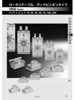
1 Compact Guide CylinderSeries MGP 12, 16, 20, 25, 32, 40, 50, 63, 80, 1008-19-3MX MTSMY CY MG CX D--X20-Data1. Top mounting3. T-slot side mountingEasy adjustment of workpiece and Cylinder mounting4. bottom mounting2. Side mountingSlide bearingThe lateral withstand load is more than twice that of a conventional stopper Cylinder (round bar type), and is suitable for use with lateral loads accompanied by impact, as in bushing bearingSuitable for use as a pusher and Top ported2. Side ported Easy positioningKnock pin holes provided on each mounting surface10202530405075100125150175200 Stroke (mm)Bore size(mm)Bearing typeMGPMS lide bearingMGPLBall bushing bearing Stroke Variations 250300350400 Intermediate strokeSpacer installation typeAvailable by the 1 mm & 5 mm body (-XB10)in stroke increments of 1 mm1.
2 Top mounting3. T-slot side mounting2. Side mounting4. bottom mounting1. Auto switch mounting1. Top port2. Side port1. Auto switch mounting Long strokes up to 400 mm are Guide CylinderSeries MGPMade to Order1. Intermediate stroke (Using exclusive body)2. With air cushion/Intermediate stroke (Spacer type)3. Heat resistant cylinder4. Low speed cylinder5. Fluoro rubber seals6. With heavy duty scraper7. With coil scraper8. Adjustable stroke Cylinder /Adjustable extension type9. Adjustable stroke Cylinder /Adjustable retraction type10. Stainless steel piston rod & plate, mounting styles providedFour mounting styles providedPiping is possible from two directions Piping is possible from two directions Auto switches can be mounted on two switches can be mounted on two sides.
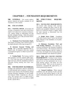
3 12, 16, 20, 25, 32, 40, 50, 63, 80, 100 Two types of Guide rod bearing to accommodate various applications8-19-4255075100125150175200 Stroke (mm)Bore size(mm)Bearing typeMGPSS lide bearing Stroke Variations 250 300 350 400 255075100125150175200 Stroke (mm)Bore size(mm)Bearing type Stroke Variations Series Variations Anti-lateral load: 10% increase Eccentric load resistance: 25% increase Impact load resistance: 140% increase(Compared with MGPM50 Compact Guide Cylinder ) Bore size(mm) Guide rod diameter (mm)MGPS3045 MGPM25305080 With end lock type addedMGPMS lide bearingMGPLBall bushing bearing20253240506380100 Rod endlockHead endlock5080 Heavy duty Guide rod type with improved load resistanceIntermediatestrokeLockdirectio nNon-lock typeLocktypeManualreleaseSpacer typeavailableby the 5 (mm)Bore size(mm)
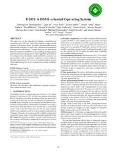
4 Bearing type Stroke Variations250300350400 Cushion valve is built into the body With air cushion type standardizedMGPMS lide bearingMGPLBall bushing bearing1620253240506380100 Intermediate strokeStrokes available by the 1 mm interval by changing the bearingBall bushing bearingSlide bearingSeriesBearing typeCushion32 4050 638010016 20 25 Bore size (mm)12 Standard typeMGPWith air cushionMGPH eavy duty Guide rod typeMGPSWith end lockMGPR ubberbumperRubberbumperAir cushion Clean Series : 12 to 63 Water resistant: 20 to 100 Note) Copper-free: 12 to 100 Copper-free (20-) RubberbumperBall bushing bearingHigh precision ball bushing bearing typeMGPAR ubberbumperHolds the Cylinder ,s home position even if the air supply is cut body 20 to 63 Body length for standard + 25 mm 80, 100 Standard + 50 mm body length An air cushion has been added to the Compact Guide Cylinder to suppress vibration and noise at the stroke end.
5 It can absorb nearly three times as much kinetic energy as a rubber ) Available with 20 to 100 slide bearing type only8-19-5MX MTSMY CY MG CX D--X20-DataC DBypass port Never place your hands or fingers between the plate and the very careful to prevent your hands or fingers from getting caught in the gap between the Cylinder body and the plate when air is Do not scratch or gouge the sliding portion of the piston rod and the Guide seals, etc. will result in leakage or bottom of cylinderThe Guide rods protrude from the bottom of the Cylinder at the end of the retracting stroke, and therefore, in cases where the Cylinder is to be bottom mounted, it is necessary to provide bypass ports in the mounting surface for the Guide rods, as well as holes for the hexagon socket head screws which are used for , in applications where impact occurs from a stopper, etc.
6 , the mounting bolts should be inserted to a depth of 2 d or more ( d or more for MGPS).Caution1. Keep the adjusting range of the cushion valve within 3 rotations of the completely closed adjusting the cushion valve, use the following screwdriver or hexagon wrenches. Keep the adjusting range of the cushion valve within 3 rotations of the completely closed position. Air leakage will occur if operated after opening by 4 rotations or more. Furthermore, a stopper mechanism is provided for the cushion valve, and it should not be forced open beyond that size(mm)A (mm) B (mm) C (mm) 121620253240506380100 DMGPMMGPLH exagon socket head cap screw50567282981061301421802101822243034 4046585462414654647886110124156188101214 182222272733398101215181822222833M4 x x x x x x x x x x (mm) 2 d or more(d = Thread )C DBypass port MGPBore size(mm)A (mm) B (mm) C (mm) 5080 Hexagon socket head cap screw1402145066116170M12 x x 2 Series MGPSWith air cushion2.
7 Be sure to activate the air cushion at the Cylinder stroke sure to activate the air cushion at the end of the Cylinder stroke. When it is intended to operate with the cushion valve fully opened, select a Cylinder equipped with rubber bumper. If operated without confirming this point, the piston rod assembly, etc., may be Be sure to operate a Cylinder equipped with air cushion to the end of the it is not operated to the end of the stroke, the effect of the air cushion will not be fully exhibited. Consequently, in cases where the stroke is regulated by an external stopper, etc.
8 , caution must be exercised, as the air cushion may become completely (mm) 3247 Bore size (mm)1620, 25, 32, 4050, 6380, 100 Applicable toolFlat head watchmakers, screwdriver 3 mmJIS B 4648 hexagon wrench key B 4648 hexagon wrench key B 4648 hexagon wrench key d or more(d = Thread )CushionDepending on the operating conditions, piping port positions can be changed by using a For M5 After tightening by hand, tighten additional 1/6 to 1/4 rotation with a tightening For taper threadUse the correct tightening torques listed below. Before tightening the plug, wrap pipe tape around it.
9 Also, with regard to the sunk dimension of a plug (a dimension in the drawing), use the stipulated figures as a Guide and confirm the air leakage before operation. If tightening plugs on the top mounting port with more than the proper tightening torque, plugs will be screwed much deeply and air passage will be squeezed. Consequently, the Cylinder speed will be to 912 to 1422 to 24 Connection threadsizeProper tightening torque (N m) mm or less1 mm or less1 mm or lessa dimensionaPlugSeries MGPS pecific Product PrecautionsBe sure to read before handling. 8-19-6 CautionCautionCautionCautionCaution This is necessary for the correct locking and unlocking air pressure of MPa or higher to the port on the side that has the lock mechanism, as it is necessary for disengaging the the pressure on the side with the lock mechanism drops to MPa or below, the lock engages automatically.
10 If the piping on the side with the lock mechanism is thin and long, or if the speed controller is away from the Cylinder port, the lock engagement may take some due to decline of the exhaust speed. The same result will be caused by clogging of the silencer installed at the EXH port of the solenoid end lockRod end releasing the lock, be sure to supply air to the side without the lock mechanism, so that there is no load applied to the lock mechanism when it is released. If the lock is released when the port on the other side is in an exhaust state, and with a load applied to the lock unit, the lock unit may be subjected to an excessive force and be damaged.