Transcription of Complete Fixture Assembly - Cooper Industries
1 Decorative CoverEndcap (L)Endcap (R)Knuckle Arm(Power feed)Knuckle Arm(Non-power feed)Knuckle BaseHousing ExtrusionAcrylic Lens CordConnectorWallplate (Power feed)Wallplate(Non-Power feed)10-32 X 7/8"Socket Cap Screw10-32 X 3/4" Socket CapScrewWallplate Cover8-32 PhillipsLocking O-RingNippleCord ConnectorNote: 5/32" Allen wrench and Phillips screw driver are required (suppliedby others).GasketComplete Fixture Assembly ( Fixture lengths vary dependingon lamp type; see lamp chart on page 2)Exploded ViewNote: All RC3 mounting is field adjustableInstallation InstructionsBASE MOUNTWALL MOUNTCANTILEVER MOUNTT hese installation instructions are valid with the above Arrowlinear mounting : Before starting any work ensure that all sources of power are turned off. All work must meet local/national codes and be performed by a certified electrician. Do not mount fixtures vertically. Indoor fixtures cannot be used for outdoor AK: BASE, WALL, CANTILEVER,CEILINGS heet 1 of 3 ADY110992 REV A(ECN: CL-151056)CEILING MOUNTL engthMounting the Fixture BracketsCLCLI nstallation InstructionsBASE MOUNTWALL MOUNTCANTILEVER MOUNTT hese installation instructions are valid with the above Arrowlinear mounting : Before starting any work ensure that all sources of power are turned off.
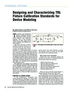
2 All work must meet local/national codes and be performed by a certified electrician. Do not mount fixtures vertically. Indoor fixtures cannot be used for outdoor AK: BASE, WALL, CANTILEVER,CEILING,Sheet 2 of 3 CEILING REV A(ECN: CL-151056)Prior to Roughing in J-Boxes:1. Determine the location of Fixture mounting and verifystructure will support the weight of the fixtures . If necessary, use additional bracing to support Using mounting plate centers provided in lamp chart, attach mounting arms to Fixture Assembly (ref. figure 1). 3. Install J-Boxes (by others)(ref. figure 2). Mounting Arm to Fixture Assembly1. Attach arm and knuckle to the wallplate using the 1" nipple and o-ring (be careful not to over compress the o-ring). 2. Once the wallplate arm Assembly (Power Feed or Non Power) is assembled, place the Knuckle base horizontally into extrusion track located on back of the Rotate the Complete wallplate arm Power Feed Assembly counter- clockwise 90; and the Non-Power Assembly clockwise Adjust Mounting Arms horizontally to match the desired mounting location and tighten the 10-32 X 3/4"Socket Cap screw; use lamp chart for recommended standard Chart Note: 12FT fixtures do require a middle arm.
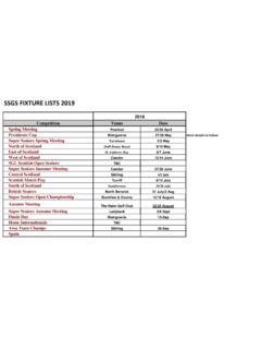
3 (See lamp chart)J-Box(By others)WallplateAccess Cover2 x 1/4" Fasteners(By others)Knuckle Arm(Power Feed)Knuckle BaseMounting Power-Side Assembly1. Once the mounting arms have been completely assembled,using appropriate 1/4" fasteners (by others), secure mounting plate over the J-box. If necessary, use additional bracing to support Use the access cover to allow you to wire the Fixture power to the main power inside the J-box, making sure to re-attach theaccess cover when finished. Power CordNote: Fixture not shown for Housing ExtrusionCord ConnectorWallplate(Power feed)10-32 X 3/4"Socket CapScrewAvailable LengthsAvailable WattagesAvailable Lamp Types Mounting plate centers in(mm)1FT12W(LED)CENTER2FT22W(LED)2FT14W (T5)2FT17W(T8)2FT24W (T5 HO)3FT33W(LED)3FT21W(T5)3FT25W(T8)3FT39W (T5 HO)4FT44W(LED)4FT28W(T5)4FT32W(T8)4FT54W (T5 HO)6FT2 X 33W(LED )6FT2 X 21W(T5 )6FT2 X 25W(T8)6FT2 X 39W(T5 HO)8FT2 X 44W(LED)8FT2 X 28W(T5)8FT2 X 32W(T8)8FT2 X 54W(T5 HO)12FT3 X 28W(LED)12FT3 X 28W(T5)12FT3 X 32W(T8)12FT3 X 54W(T5 HO)22 - 13/16IN (580m m )34 - 5/8IN (880m m )46 - 7/16IN (1180m m )72 - 29/32IN (1852m m )96 - 17/32IN (2452m m )146 - 27/64IN(3719m m )M IDDLE AR M73 - 7/32N (1860m m )434"12145 214"5745 Wallplate (Power feed)J-Box(by others)Cord Connector(Supplied)Power Cord(Supplied)Decorative Cover(Supplied)Power cord wire connection (Wire nuts by others)(Side View)
4 AK 24"AK 6"AK 12"AK 18"Mounting Plate Dimensions: in [mm]Note: Arrowlinear Wallplates are designed to accommodate 1/4" mounting hardware (by others) Hardware must meet Local / Nationalcodes and installation must be provided by a licensed contractor. (Front View)Power Feed 1. Wire the power cord (supplied) to the inside of the Fixture by running the power cord through the endcap and out the back through the cord Attach all wires and ensure all connections are properly matched. Hide wires inside the Fixture and attach Decorative Cover using 10-32 X 1/2" Socket Cap InstructionsBASE MOUNTWALL MOUNTCANTILEVER MOUNTT hese installation instructions are valid with the above Arrowlinear mounting : Before starting any work ensure that all sources of power are turned off. All work must meet local/national codes and be performed by a certified electrician. Do not mount fixtures vertically.
5 Indoor fixtures cannot be used for outdoor AK: BASE, WALL, CANTILEVER, CEILING,Sheet 3 of 3 ADY110992 REV A(ECN: CL-151056)CEILING MOUNTW allplate(Non-Power feed)7132"179