Transcription of Compression Connector System - TNB.COM
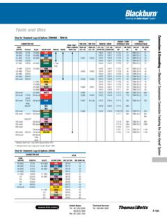
1 CompressionConnectorSystemStep OnePreparing the CableWire Stripper shown is Part No. the insulation to the proper length sothat conductors can be fully inserted into theconnector Length Too LongStrip Length Too ShortStrip Length Just RightStrip the insulation carefully to avoid nickingor cutting conductors (wire brush if required).StrandsCutNickedStrandsGoodStr ip33 Step TwoDetermining the Proper ConnectorDetermine the proper Color-Keyed Connectorfor the cable size being used. connectors marked with just cable size or CUshould be used on copper conductors only. connectors marked AL9 *with the cable sizeshould be used on aluminum conductors only. connectors marked AL9CU with the cablesize may be used on the aluminum orcopper conductors.* Aluminum lugs with a 9 indicate 90oC are marked to show cable SizeStep ThreeChoosing Tool and Proper DieBattpac Tool TBM62 BSCR the proper installingdie and appropriate connectors have colored bandsor colored dots that correspond tocolor markings on the and dies also have a diecode number marked or stamped onthem.
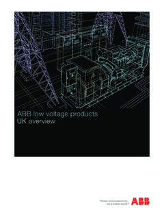
2 Dies have a code numberengraved in the crimp surfaceColored CodesColored BandsDie Code MarkingColored StripDie Code Engraving77 Locate tool with correctdie in proper positionon Connector andactivate connectors are banded bycolored stripes or engraving toindicate location of die onconnector for Compression . AluminumDie locatedON BandsCopperDie locatedBETWEEN bandsStep FourInstallation and InspectionBattpac Battery Powered Compression TBM62 BSCR properly crimped, the die code number will be embossed on the Connector for easy inspection to determine if correct dieand Connector combination were & Betts uses full-width and half-width dies dependenton Connector size and tool used. Half-width dies are markedwith the letter H after thedie code to the instruction sheetsupplied with the connectorsfor information regarding striplength, die selection and numberof compressions making multiplecrimps, make the first crimpnearest the tongue and worktowards the barrel crimp2nd crimpDie location for compressionColored bandsDie code embossed99 Connector SizeTBM25 STBM4 STBM8-750/-1 TBM-8 / 8 STBM-5 / 5 STBM6 / 6S (25000)13642M (13400) Hydraulic HeadTBM12 Hydraulic HeadCopperFlex/24AL/CUTBM8 Die Cat.
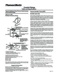
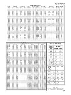
3 No. TBM5 Die Cat. No. Upper DieCat. No. Lower DieDie Cat. Code Cat. Code AWG37/2410 AWGRed13475134771173221 TBM12D-1216 AWG61/248 AWGB lueorderorder13475134771173324 TBM12D-1244 AWG91/246 AWGGray134611345413472134761173429 TBM12D-2292 AWG 125/24 Brown13474134771173533 TBM12D-2331 AWG150/244 AWGG reenC-TAPS ONLY13474134771173637 TBM12D-3371/0225/242 AWGP inkorderorder13475134771173742 TBM12D-3422/0275/24 Black134621345513474134771173845 TBM12D-4453/0325/24 Orange13474134771173950 TBM12D-4504/0450/24 Purpleorderorder13475134771174054 TBM12D-554250 MCM550/24 Yellow134631345613473134761177162 TBM12D-5621 AWGGold13474134771173845 TBM12D-4451/0 Tanorderorder13474134771173950 TBM12D-4502/0 Olive134641345713475134771174054 TBM12D-5543/0 Ruby13473134761174160 TBM12D-560300 MCM4/0 White1346513473134761174266 HTBM12D-566H350 MCM775/24 (short)250 MCMRed134661345813472134761174371 HTBM12D-471H400 MCM775/24 (long)300 MCMBlue134674/0 only13472134761174476 HTBM12D-476H925/24*N/A13479134761174580H N/A500 MCM350 MCMB rown13468134781347811746-TB87 HTBM12D-387H600 MCM1100/24400 MCMG reen1174794 HTBM12D-394 HGreen94H1325/24**Pink700 MCM500 MCMPink1174899 HTBM12D-299H750 MCM650 MCMB lack11749106 HTBM12D-2106H800 MCMO range11750107H700 MCMP urple11751112 HTBM12D-1112H900 MCM1925/24750 MCMY ellow11753115 HTBM12D-1115H1000 MCM800 MCM1000 MCMTool and Die Selection chart for Power connectors *Standard barrel only.
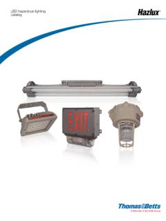
4 Long barrel requires Brown 87H **Standard barrel only. Long barrel requires Black 106H Color KeyedDie Groove10 Connector SizeTBM6 BSCR/6 HTBM62 BSCRTBM14 BSCR / 14M / 13100 ATBM15 BSCR / 15I**21940 (40 TON)Code CopperFlex/24AL/CUDie Cat. No. Die Code Cat. Code Cat. Code Cat. Code Cat. Code AWG37/2410 AWGRed6 TON2121 TBM622121155202115520216 AWG61/248 AWGBlue6 TON2424 TBM622424155222415522244 AWG91/246 AWGGray6 TON2929 TBM62292915527-CK2915527-CK2911401292 AWG 125/24 Brown6 TON3333 TBM6233331552833155283311402331 AWG150/244 AWGG reen6 TON3737 TBM62373715513-CK3715513-CK3711333371/02 25/242 AWGPink6 TON4242 TBM62424215508421550842H11334422/0275/24 Black6 TON4545 TBM6245451552645155264511405453/0325/24 Orange6 TON5050 TBM6250501553050155305011406504/0450/24 Purple6 TON5454 TBM62545415511541551154H1140754H250 MCM550/24 Yellow6 TON6262 TBM62626215510-CK6215510-CK62297-31669-7 621 AWGGold6 TON4545 TBM6245451552645155264511405451/0 Tan6 TON5050 TBM6250501553050155305011406502/0 Olive6 TON5454 TBM62545415511541551154H11407543/0 Ruby6 TON6060 TBM62606015532-CK6015532-CK601140860300 MCM4/0 White6 TON6666 HTBM6266661553466H1553466H1140966350 MCM775/24 (short)
5 250 MCMRed6 TON7171 HTBM62717115514-CK71H15514-CK71H11363714 00 MCM775/24 (long)300 MCMBlue6 TON7676 HTBM6276761551276H1551276H1141076925/24* N/A6 TON8080 HTBM6280801551780H1551780HN/A1560680500 MCM350 MCMB rown6 TON8787 HTBM6287871550687H1550687H1142387600 MCM1100/24400 MCMG reen6 TON9494H1561194H1136494 Green15536-CK94H15536-CK94H1325/24**Pink 700 MCM500 MCMPink99H1550599H1550599H1142499750 MCM650 MCMB lack106H15515-CK106H15515-CK106H74506106 800 MCMO range107H15608107H11425107700 MCMP urple112H15609112H11426112900 MCM1925/24750 MCMY ellow115H15504115H15504115H113081151000 MCM800 MCM15603125H114161251000 MCM15602140H1141814015601150H11419150 Tool and Die Selection chart for Power connectors *Standard barrel only. Long barrel requires Brown 87H **Standard barrel only. Long barrel requires Black 106H **15500 Series dies require 15500-TB adapter. 15500F for full size die to fit TBM151 without adapterColor KeyedDie Groove1112 Conductor Size Code Cable (Flex Cable)InstallationMainBranch 1 Branch 2 Branch 3H-TapColorDieTool# Of CrimpsDie EmbossingStrip LengthInsulating Cover8-14 (8-14)8-14 (8-14)--CHT814-10 Green15CA37 RCH*Group 1137R1/2"HTC2S2-6 Str/Sol(2-8)2-6 Str / Sol (2-8)8-14 (8-14)8-14 (8-14)CHT214-9 Brown15CA71 RCH*Group1171R7/8"250-2 (4/0-2)8-14 (8-14)8-14 (8-14)-CHT250214-8 Purple15CA80 RCH*Group 2180R1 1/8"HTC40250-2 (4/0-2)2-6 Str / Sol (2-8)8-14 (8-14)-CHT25014-7 Purple15CA80 RCH*Group 2180R1 1/8"250-2 (4/0-2)250-2 (4/0-2)--CHT2502-6 Purple15CA80 RCH*Group 2180R13/16"500-4/0 (350-4/0)250-1/0 (4/0-1/0)1 Str 2-6 (1-8)8-14 (8-14)CHT50010-5 Brown15612 CHGroup 22N1 1/8"500-4/0 (350-4/0)500-4/0 (350-4/0)--CHT50040-4 Brown15612 CHGroup 22N1 1/8"750-350 (550-500)4/0-1/0 (250-1/0)1 Str 2-6 (1-8)2-14 (2-14)
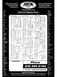
6 CHT75010-3 Yellow15620 CHGroup 21Z1 1/8"HTC500750-350 (550-500)750-350 (550-350)--CHT750350-2 Yellow15620 CHGroup 21Z1 3/8"750 (750-500)350-4/0 STR & FLEX--CHT75040-11 Yellow15620 CHGroup 21Z1 1/8"(750-500) (750)(750-500) (350)--CHT750350-1 FWhite15620 CHFG roup 21F1 1/8"HTC1000 Tool and Die Selection chart for Copper H-Taps*Requires optional adapter 15500-TB when used with hydraulic head TBM15I and TBM15 BSCR Group 1 = TBM15I, TBM15 BSCR, TBM14, TBM14 BSCR, 13100 AGroup 2 = TBM15I, TBM15 BSCR13** When using 3 AWG on main and 12 AWG on branch with smart tools and dies, 12 AWG wire must be doubled (hair-pinned) and placed on branch for crimpingGroup 1 = TBM6H / TBM6 BSCRG roup 2 = TBM25S, TBM21E and require 2 compressions within each crimp areaGroup 3 = TBM5 / 5S, TBM6 / 6S, TBM8/8S, TBM6H and require 1 Compression within each crimp areaTool and die chart for Standard C-TapsCode Wire Comb. Cir. Area RangeGroup 1 TBM62 BSCRTBM8-750 Group 2 Group 3 Insulation ChoiceMainBranch 1C-TapColorDieDieDieAdhesive PadShrink Tubing121454705 Red6 TON21 TBM6221-1416101054710 Blue6 TON24 TBM6224HS12-6812610,1254715 Gray6 TON29 TBM6229-88,10,124 OR 58, 10, 1254720 Brown6 TON33 TBM6233 TBM8-750C2066, 836, 8, 10, 12 **54725 Green6 TON37 TBM6237 TBM8-750C25304 OR 56, 5HS6-126, 8, 10, 1254730 Pink6 TON42 TBM6242 TBM8-750C253035AC5X34314, 5, 6, 8, 10, 1254735 Black6 TON45 TBM6245 TBM8-750C354024, 533, 41/04, 5, 6, 8, 10, 1254740 Orange6 TON50 TBM6250 TBM8-750C354013, 422, 3HS4-302/03, 4, 5, 6, 8, 10, 1254745 Purple6 TON54 TBM6254 TBM8-750C45501/02, 311, 33/02, 3, 4, 5, 6, 8, 10, 1254750 Yellow6 TON62 TBM6262 TBM8-750C45502/01, 21/01/0, 1 Accommodates this RangeAccommodates this Entire Range14 Tool and die chart for Large C-Taps*For tin plate finish add "TP" to Cat.
7 No. listed (Example: 54755TP) **Use with adapter Cat. No. 15500-TB (Note: If 15500 dies have a suffix "F", they are full sized dies and can be used with the TBM15I without an adapter.) **When usingcompact copper cable, apply additional overlappingcrimps so that C-tap is crimped from end to end. 11000 series dies go with 13642M tool, TBM12D-# series dies go with TBM12 tool, and 15500 series dies go with TBM14M/14 BSCR/13100A/TBM15I/15 BSCR **#6 AWG branch must be doubledCode Copper RangeRegular ToolsSmart ToolInsulation ChoiceMainBranch 1C-Tap *ColorToolsDiesDie Code# Of Crimps**ToolsDie# Of CrimpsAdhesive PadShrink Tubing1154755 Blue13642M1174476H2 TBM8-750 TBM8-750CL11/01/0-2 TBM12 TBM12D-4 TBM8-750M-12/02/0-4 TBM14M7613/01/0-6 TBM15I15512 **4/01-813100A2/02/0-154760 BrownTBM14 BSCR11746-TB87H223/03/0-3 TBM15 BSCRTBM12D-3HS4-304/04/0-42501/0-815506 **2/02/0-154765 Pink1174899H3/03/0-2 TBM12D-24/04/0-42503/0-615505 **3002/0-84/04/0-2/054770 Black11749106 HAC5X7250250-1 TBM12D-23004/0-43503/0-615515-CK **25025054775 Yellow11753115 HHS40-400300300-3/0 TBM12D-1350350-1/0400300-215504 **450250-4500250-6**350350-4/054780 WhiteTBM15I15603125H400400-2/0 TBM15 BSCR450450-1500500-2N/AHS500-10007504/0- 65478535004/0-1/0N/A4750/500750-4/054790 15 Conductor PropertiesConductors
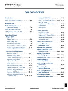
8 Direct-Current Resistance at 75 C (167 F)StrandingOverallCopperAluminumSizeArea DiameterDiameterAreaUncoatedCoated(AWG or kcmil)mm2 Circular Properties (Continued)Conductors Direct-Current Resistance at 75 C (167 F)StrandingOverallCopperAluminumSizeArea DiameterDiameterAreaUncoatedCoated(AWG or kcmil)mm2 Circular : The construction information is per NEMA WC8-1992 or ANSI/UL 1581-1998. The resistance is calculated per National Bureau of StandardsHandbook 100, dated 1966, and Handbook 109, dated 625 TABLESNATIONAL ELECTRICAL CODE, 2002 Edition17 Table Ampacities of Two or Three InsulatedConductors, Rated 0 Through 2000 Volts, Within an OverallCovering (Multiconductor Cable), in Raceway in Free AirBased on Ambient Air Temperature of 30 C (86 F)Temperature Rating of Conductor. (See Table )60 C75 C90 C60 C75 C90 C(140 F)(167 F)(194 F)(140 F)(167 F)(194 F)TypesTypesTHHN,THHN,THHW,THHW,THW-2,TH W-2,TypesTHWN-2,THWN-2,RHW,RHH,TypesRHH, THHW,RWH-2,RHW,RWH-2,THW,USE-2,THHW,USE- 2,THWN,XHHN,THW,XHHW,TypesXHHW,XHHW-2,TH WN,XHHW-2,TW, UFZWZW-2 TypeTWXHHWZW-2 SizeSize(AWG orALUMINUM OR(AWG orkcmil)COPPERCOPPER-CLAD ALUMINUM kcmil)1416*18*21*14 1220*24*27*16*18*21*121027*33*36*21*25*2 8*1083643482833 37 864858653845 51 646679895161 69 4376901025970793288105119698393211021211 37809510611/0121145163941131271/02/01381 661861081291462/03/01581892141241471673/ 04/01872232531471761974/0250205245276160 1922172503002342813171852212503003502553 0534520224227335040027432837121826129540 0500315378427254303342500600343413468279 3353786007003764525143103714207007503874 6652932138443575080039747954333139745080 0900415500570350421477900100044854261738 24605211000 Correction ( C)( F)
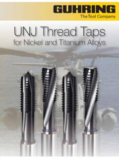
9 21 7726 8631 9536 10441 11346 12251 13156 60 14061 70 15871 80 176*Unless otherwise specifically permitted elsewhere in this Code, theovercurrent protection for these conductor types shall not exceed15 amperes for 14 AWG, 20 amperes for 12 AWG, and 30amperes for 10 AWG copper; or 15 amperes for 12 AWG and 25amperes for 10 AWG aluminum and copper-clad : NEC2002 For ambient temperatures other than 30 C (86 F), multiply theampacities shown above by the appropriate factor shown and Tubing Fill Tables forConductors and Fixture Wires of theSame SizeTable C1 Maximum Number of Conductors orFixture Wires in Electrical Metallic Tubing (EMT) (Based on Table 1, Chapter 9)CONDUCTORSC onductorMetric Designator (Trade Size)Size162127354153637891103 Type(AWG/kcmil)(d)(f)(1)(1b)(1d)(2) (2d)(3)(3d)(4)RHH,1447112027468012015720 1 RHW,1236917233866100131167 RHW-210258131830538110513581247916284255 706113581322344456411246101726344431 1 1 4 5 91523303821 1 1 3 4 713202633101113591317221/001112471115192 /001112461013173/00011135811144/00011135 7912250000111357930000011135683500001113 4674000001112457500000011234660000001113 4570000000112347500000011234800000001123 4900000001113310000000011123TW,148152543 5896168254332424 THHW,1261119334574129195255326 THW,10581424335596145190243 THW-282581318305381105135 RHH*,146106283964112169221282 RHW*,12481323315190136177227 RHW-2*,103610182440701061381778146101424 426383106 SOURCE.
10 NEC200219 Conduit and Tubing Fill Tables forConductors and Fixture Wires of theSame SizeTable C1 (Continued)CONDUCTORSC onductorMetric Designator (Trade Size)Size162127354153637891103 Type(AWG/kcmil)(d)(f)(1)(1b)(1d)(2) (2d)(3)(3d)(4)RHH*,61348111832486381 RHW*,4113681324364760 RHW-2*,3113571220314052TW, THW,2112461017263444 THHW,111134712182431 THW-21/0011236101620262/001113591317223/ 001112471115194/000111369121625000111357 1013300001112468113500001114671040000011 1357950000011134676000001112346700000011 1345750000011134580000001113359000000011 23410000000011234 THHN,141222356184138241364476608 THWN,12916264561101176266347443 THWN-21051016283863111167219279836916223 66496126161624712162646699111641 2 4 7101628435671311368132436476021135711203 0405111 1 1 4 5 8152229371/0111347121925322/001123610162 0263/001113581317224/0011124711141825000 1113691115300001113571013350001112469114 0000011146810500000111356860000011124577 0000011123467500000111345800000011134590 00000