Transcription of Computer Architecture: Main Memory (Part I)
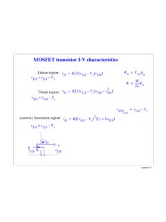
1 Computer Architecture: Main Memory (Part I)Prof. Onur MutluCarnegie Mellon University(reorganized by Seth)Main MemoryMain Memory in the System3 CORE 1L2 CACHE 0 SHARED L3 CACHEDRAM INTERFACECORE 0 CORE 2 CORE 3L2 CACHE 1L2 CACHE 2L2 CACHE 3 DRAM BANKSDRAM Memory CONTROLLERI deal Memory Zero access time (latency) Infinite capacity Zero cost Infinite bandwidth (to support multiple accesses in parallel)4 The Problem Ideal Memory s requirements oppose each other Bigger is slower Bigger Takes longer to determine the location Faster is more expensive Memory technology: SRAM vs. DRAM Higher bandwidth is more expensive Need more banks, more ports, higher frequency, or faster technology5 Memory Technology: DRAM Dynamic random access Memory Capacitor charge state indicates stored value Whether the capacitor is charged or discharged indicates storage of 1 or 0 1 capacitor 1 access transistor Capacitor leaks through the RC path DRAM cell loses charge over time DRAM cell needs to be refreshed Read Liu et al.
2 , RAIDR: Retention-aware Intelligent DRAM Refresh, ISCA enable_bitline Static random access Memory Two cross coupled inverters store a single bit Feedback path enables the stored value to persist in the cell 4 transistors for storage 2 transistors for accessMemory Technology: SRAM7row selectbitline_bitlineAn Aside: Phase Change Memory Phase change material (chalcogenide glass) exists in two states: Amorphous: Low optical reflexivity and high electrical resistivity Crystalline: High optical reflexivity and low electrical resistivity8 PCM is resistive Memory : High resistance (0), Low resistance (1)Lee, Ipek, Mutlu, Burger, Architecting Phase Change Memory as a Scalable DRAM Alternative, ISCA Bank: A Fundamental Concept Interleaving (banking) Problem: a single monolithic Memory array takes long to access and does not enable multiple accesses in parallel Goal: Reduce the latency of Memory array access and enable multiple accesses in parallel Idea: Divide the array into multiple banks that can be accessed independently (in the same cycle or in consecutive cycles) Each bank is smaller than the entire Memory storage Accesses to different banks can be overlapped An issue.
3 How do you map data to different banks? ( , how do you interleave data across banks?)9 Memory Bank Organization and Operation Read access sequence:1. Decode row address & drive word-lines2. Selected bits drive bit-lines Entire row read3. Amplify row data4. Decode column address & select subset of row Send to output5. Precharge bit-lines For next access10 Why Memory Hierarchy? We want both fast and large But we cannot achieve both with a single level of Memory Idea: Have multiple levels of storage (progressively bigger and slower as the levels are farther from the processor) and ensure most of the data the processor needs is kept in the fast(er) level(s)11 Memory Hierarchy Fundamental tradeoff Fast Memory : small Large Memory : slow Idea: Memory hierarchy Latency, cost, size, bandwidth12 CPUMainMemory(DRAM)RFCacheHard DiskA Modern Memory Hierarchy13 Register File32 words, sub nsecL1 cache~32 KB, ~nsecL2 cache512 KB ~ 1MB, many nsecL3 cache.
4 Main Memory (DRAM), GB, ~100 nsecSwap Disk100 GB, ~10 msecmanual/compilerregister spillingautomaticdemand pagingAutomaticHW cachemanagementMemoryAbstractionThe DRAM SubsystemDRAM Subsystem Organization Channel DIMM Rank Chip Bank Row/Column15 Page Mode DRAM A DRAM bank is a 2D array of cells: rows x columns A DRAM row is also called a DRAM page Sense amplifiers also called row buffer Each address is a <row,column> pair Access to a closed row Activatecommand opens row (placed into row buffer) Read/writecommand reads/writes column in the row buffer Prechargecommand closes the row and prepares the bank for next access Access to an open row No need for activate command16 DRAM Bank Operation17 Row Buffer(Row 0, Column 0)Row decoderColumn muxRow address 0 Column address 0 DataRow 0 Empty(Row 0, Column 1)Column address 1(Row 0, Column 85)Column address 85(Row 1, Column 0)
5 HITHITRow address 1 Row 1 Column address 0 CONFLICT !ColumnsRowsAccess Address: The DRAM Chip Consists of multiple banks (2-16 in Synchronous DRAM) Banks share command/address/data buses The chip itself has a narrow interface (4-16 bits per read)18128M x 8-bit DRAM Chip19 DRAM Rank and Module Rank: Multiple chips operated together to form a wide interface All chips comprising a rank are controlled at the same time Respond to a single command Share address and command buses, but provide different data A DRAM module consists of one or more ranks , DIMM (dual inline Memory module) This is what you plug into your motherboard If we have chips with 8-bit interface, to read 8 bytes in a single access, use 8 chips in a DIMM20A 64-bit Wide DIMM (One Rank)21A 64-bit Wide DIMM (One Rank) Advantages: Acts like a high-capacity DRAM chip with a wide interface Flexibility.
6 Memory controller does not need to deal with individual chips Disadvantages: Granularity: Accesses cannot be smaller than the interface width22 Multiple DIMMs23 Advantages: Enables even higher capacity Disadvantages: Interconnect complexity and energy consumption can be highDRAM Channels 2 Independent Channels: 2 Memory Controllers (Above) 2 Dependent/Lockstep Channels: 1 Memory Controller with wide interface (Not shown above)24 Generalized Memory Structure25 Generalized Memory Structure26 Kim+, A Case for Exploiting Subarray-Level Parallelism in DRAM, ISCA DRAM SubsystemThe Top Down ViewDRAM Subsystem Organization Channel DIMM Rank Chip Bank Row/Column28 The DRAM subsystemMemory channelMemory channelDIMM (Dual in line Memory module)Processor Channel Breaking down a DIMMDIMM (Dual in line Memory module)Side viewFront of DIMMBack of DIMMB reaking down a DIMMDIMM (Dual in line Memory module)Side viewFront of DIMMBack of DIMMRank 0.
7 Collection of 8 chipsRank 1 RankRank 0 (Front)Rank 1 (Back)Data <0:63>CS <0:1>Addr/Cmd<0:63> <0:63> Memory channelBreaking down a RankRank 0<0:63>Chip 0 Chip 1 Chip 7..<0:7> <8:15> <56:63>Data <0:63>Breaking down a ChipChip 0<0:7>Bank 0<0:7> <0:7> <0:7>..<0:7>Breaking down a BankBank 0<0:7>row 0row 16k (column)1 BRow <0:7>DRAM Subsystem Organization Channel DIMM Rank Chip Bank Row/Column36 Example: Transferring a cache cache blockPhysical Memory spaceChannel 0 DIMM 0 Rank 0 Example: Transferring a cache cache blockPhysical Memory spaceRank 0 Chip 0 Chip 1 Chip 7<0:7> <8:15> <56:63>Data <0:63>..Example: Transferring a cache cache blockPhysical Memory spaceRank 0 Chip 0 Chip 1 Chip 7<0:7> <8:15> <56:63>Data <0:63>Row 0 Col 0.
8 Example: Transferring a cache cache blockPhysical Memory spaceRank 0 Chip 0 Chip 1 Chip 7<0:7> <8:15> <56:63>Data <0:63>8 BRow 0 Col 0..8 BExample: Transferring a cache cache blockPhysical Memory spaceRank 0 Chip 0 Chip 1 Chip 7<0:7> <8:15> <56:63>Data <0:63>8 BRow 0 Col 1..Example: Transferring a cache cache blockPhysical Memory spaceRank 0 Chip 0 Chip 1 Chip 7<0:7> <8:15> <56:63>Data <0:63>8B8 BRow 0 Col 1..8 BExample: Transferring a cache cache blockPhysical Memory spaceRank 0 Chip 0 Chip 1 Chip 7<0:7> <8:15> <56:63>Data <0:63>8B8 BRow 0 Col 1A 64B cache block takes 8 I/O cycles to the process, 8 columns are read ..Latency Components.
9 Basic DRAM Operation CPU controller transfer time Controller latency Queuing & scheduling delay at the controller Access converted to basic commands Controller DRAM transfer time DRAM bank latency Simple CAS (column address strobe) if row is open OR RAS (row address strobe) + CAS if array precharged OR PRE + RAS + CAS (worst case) DRAM Controller transfer time Bus latency (BL) Controller to CPU transfer time44 Multiple Banks (Interleaving) and Channels Multiple banks Enable concurrent DRAM accesses Bits in address determine which bank an address resides in Multiple independent channels serve the same purpose But they are even better because they have separate data buses Increased bus bandwidth Enabling more concurrency requires reducing Bank conflicts Channel conflicts How to select/randomize bank/channel indices in address?
10 Lower order bits have more entropy Randomizing hash functions (XOR of different address bits)45 How Multiple Banks Help46 Address Mapping (Single Channel) Single-channel system with 8-byte Memory bus 2GB Memory , 8 banks, 16K rows & 2K columns per bank Row interleaving Consecutive rows of Memory in consecutive banks Accesses to consecutive cache blocks serviced in a pipelined manner Cache block interleaving Consecutive cache block addresses in consecutive banks 64 byte cache blocks Accesses to consecutive cache blocks can be serviced in parallel47 Column (11 bits)Bank (3 bits)Row (14 bits)Byte in bus (3 bits)Low Col. High ColumnRow (14 bits)Byte in bus (3 bits)Bank (3 bits)3 bits8 bitsBank Mapping Randomization DRAM controller can randomize the address mapping to banks so that bank conflicts are less likely48 Column (11 bits)3 bitsByte in bus (3 bits)XORBank index (3 bits)Address Mapping (Multiple Channels) Where are consecutive cache blocks?