Transcription of Connection and Tension Member Design
1 ARCH 631 Note Set F2013abn 1 Connection and Tension Member Design Notation: A = area (net = with holes, bearing = in contact, ) Ae = effective net area found from the product of the net area An by the shear lag factor U Ab = area of a bolt Ag = gross area, equal to the total area ignoring any holes Agv = gross area subjected to shear for block shear rupture An = net area, equal to the gross area subtracting any holes, as is Anet Ant = net area subjected to Tension for block shear rupture Anv = net area subjected to shear for block shear rupture ASD = allowable stress Design d = diameter of a hole fp = bearing stress (see P)
2 Ft = tensile stress fv = shear stress Fconnector = shear force capacity per connector Fn = nominal Tension or shear strength of a bolt Fu = ultimate stress prior to failure FEXX = yield strength of weld material Fy = yield strength Fyw = yield strength of web material g = gage spacing of staggered bolt holes I = moment of inertia with respect to neutral axis bending k = distance from outer face of W flange to the web toe of fillet l = name for length L = name for length Lc = clear distance between the edge of a hole and edge of next hole or edge of the connected steel plate in the direction of the load L = length of an angle in a connector with staggered holes LRFD = load and resistance factor Design n = number of connectors across a joint N = bearing length on a wide flange steel section = bearing type Connection with threads included in shear plane p = pitch of connector spacing P = name for axial force vector, as is T R = generic load quantity (force.)
3 Shear, moment, etc.) for LRFD Design Ra = required strength (ASD) Rn = nominal value (capacity) to be multiplied by Ru = factored Design value for LRFD Design s = longitudinal center-to-center spacing of any two consecutive holes S = allowable strength per length of a weld for a given size SC = slip critical bolted Connection t = thickness of a hole or Member tw = thickness of web of wide flange T = throat size of a weld V = internal shear force Vlongitudinal = longitudinal shear force U = shear lag factor for steel Tension Member Design Ubs = reduction coefficient for block
4 Shear rupture X = bearing type Connection with threads excluded from the shear plane y = vertical distance = pi ( radians or 180 ) = resistance factor = diameter symbol = load factor in LRFD Design = safety factor for ASD = summation symbol ARCH 631 Note Set F2013abn 2 Connections Connections must be able to transfer any axial force, shear, or moment from Member to Member or from beam to column. Steel construction accomplishes this with bolt and welds. Wood construction uses nails, bolts, shear plates, and split-ring connectors.
5 Single Shear - forces cause only one shear drop across the bolt. Double Shear - forces cause two shear changes across the bolt. 2rPAPfv 222rPAPfv ARCH 631 Note Set F2013abn 3 pIVQnFareaconnectedconnector x y ya 4 2 2 12 8 p p p p p p Bearing of a Bolt on a Bolt Hole The bearing surface can be represented by projecting the cross section of the bolt hole on a plane (into a rectangle). Horizontal Shear in Composite Beams Typical connections needing to resist shear are plates with nails or rivets or bolts in composite sections or splices.
6 The pitch (spacing) can be determined by the capacity in shear of the connector(s) to the shear flow over the spacing interval, p. where p = pitch length n = number of connectors connecting the connected area to the rest of the cross section F = force capacity in one connector Qconnected area = Aconnected area yconnected area yconnected area = distance from the centroid of the connected area to the neutral axis Connectors to Resist Horizontal Shear in Composite Beams Even vertical connectors have shear flow across them.
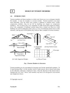
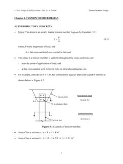
7 The spacing can be determined by the capacity in shear of the connector(s) to the shear flow over the spacing interval, p. tdPAPfp IVQpVallongitudin pIVQV allongitudin areaconnectedconnectorVQInFp ARCH 631 Note Set F2013abn 4 Tension Member Design In Tension members , there may be bolt holes that reduce the size of the cross section. Effective Net Area: The smallest effective are must be determined by subtracting the bolt hole areas. With staggered holes, the shortest length must be evaluated.
8 A series of bolts can also transfer a portion of the tensile force, and some of the effective net areas see reduced stress. Connections in Wood Connections for wood are typically mechanical fasteners. Shear plates and split ring connectors are common in trusses. Bolts of metal bear on holes in wood, and nails rely on shear resistance transverse and parallel to the nail shaft. Bolted Joints Stress must be evaluated in the Member being connected using the load being transferred and the reduced cross section area called net area.
9 Bolt capacities are usually provided in tables and take into account the allowable shearing stress across the diameter for single and double shear, and the allowable bearing stress of the connected material based on the direction of the load with respect to the grain (parallel or perpendicular). Problems, such as ripping of the bolt hole at the end of the Member , are avoided by following code guidelines on minimum edge distances and spacing. eetATorAPf ARCH 631 Note Set F2013abn 5 Nailed Joints Because nails rely on shear resistance, a common problem when nailing is splitting of the wood at the end of the Member , which is a shear failure.
10 Tables list the shear force capacity per unit length of embedment per nail. Jointed members used for beams will have shear stress across the connector, and the pitch spacing, p, can be determined from the shear stress equation when the capacity, F, is known. Other Connectors Screws - Range in sizes from #6 ( in. shank diameter) to #24 ( in. shank diameter) in lengths up to five inches. Like nails, they are best used laterally loaded in side grain rather than in withdrawal from side grain.