Transcription of CONNECTOR - jst-mfg.com
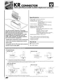
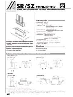
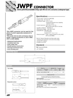
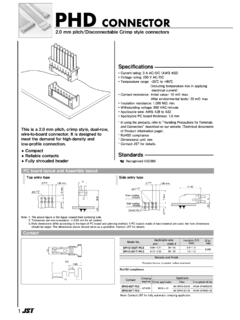
1 VL CONNECTOR . pitch/Disconnectable Crimp style connectors (Combined use for both wire -to-board and wire -to- wire connections). Specifications . Current rating: 20 A AC, DC (Refer to the following table.). 0. Voltage rating: 600 V AC, DC. T. JS. L. Temperature range: -25 C to +90 C. a (including temperature rise in applying electrical current). Contact resistance: Initial value/ 7 m max. After environmental tests/ 10 m max. Insulation resistance: 1,000 M min. Withstanding voltage: 2,000 VAC/minute Applicable wire : AWG #22 to #12. Applicable PC board thickness: mm * In using the products, refer to "Handling Precaution for Terminal and CONNECTOR " described on our website (Technical documents of Product information page).
2 * Contact JST for details. * RoHS2 compliance Note: The current rating differs depending on the number of circuits and the wire size used in each CONNECTOR . The table below lists the current rating as a function of the number of circuits and the wire size. Current unit: A. No. of wire size (AWG). circuits 12 14 16 18 20 22. This VL CONNECTOR is mm pitch wire -to- 2 20 15 10 8 6 4. 3 17 14 9 8 6 4. wire and wire -to-board CONNECTOR , designed 4 16 13 9 7 6 4. 6 15 12 8 5 3. for large current. Secondary retainer, which 8 14 11 7. 7. 6 5 3. prevents from insufficient insertion of 12 13 10 7 6 4 3.
3 Contact and coming off contact, may use Note: Do not branch in parallel current which exceeds the rated current ( more than 17A in the case of 3 circuits with AWG #12). If branched in parallel, current and large current circuit can be connected imbalance or other problems may develop. If it is absolutely necessary to branch certainly and safety. such a large current in parallel, design the circuits without causing any imbalance and provide an extra margin for each circuit. Housing lances Standards . Retainer 0 Recognized E60389. Suited for large current 1 Certified LR20812.
4 Compatible for both wire -to- wire and wire -to- board connections 2 R9351103. PC board layout and Assembly layout . <2, 3, 4 (Single-row) circuits> <4, 6, 8, 12 circuits>.. A min 4 circuits A min (Single-row) min 2, 3 circuits Inner-housing lock Inner-housing lock min .. Outer-housing lock Outer-housing lock Note: 1. The above figure is the figure viewed from soldering side. 2. Tolerances are non-cumulative: mm for all centers. 3. Hole dimensions differ according to the type of PC board and piercing method. The dimensions above should serve as a guideline. Contact JST for details.
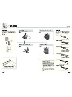
5 1. VL CONNECTOR . Contact Applicable wire Insulation Q'ty/. Model No. mm2 AWG # (mm) reel 22 16 2,000. 20 14 2,000. 12 2,000. 2 Material and Finish Phosphor bronze, tin-plated (reflow treatment). RoHS2 compliance Crimping Applicator Crimping Applicator Contact Contact machine Crimp applicator Dies Crimp applicator with dies machine Crimp applicator Dies Crimp applicator with dies MKS-L MK/SVF/M-42-20 APLMK SVF/M42-20 MKS-L MK/SVF/M-81-20 APLMK SVF/M81-20. AP-K2N.. AP-K2N. MKS-L MK/SVF/M-61-20 APLMK SVF/M61-20 Note: Contact JST for fully automatic crimping applicator.
6 Housing (Inner-housing lock). <2 circuits> <3 circuits> <4 circuits> <6 circuits> <8 circuits>. L JST. 8 7 6 5. JST L . 2 .. 1 1. 1 1 1. 4 3 2. 11. 11. 11. 11. 11. 13. 13. 13. 13. 13. <12 circuits>. L JST. 12 11 10 9 8 7. 1. 6 5 4 3 2. No. of circuits Model No. Q'ty/bag 2 VLP-02V 500. 3 VLP-03V 500. 11. 4 VLP-04V 500. 6 VLP-06V 500. 8 VLP-08V 200. 12 VLP-12V 100. 13. Material PA 66, UL94V-0, natural (white). RoHS2 compliance Note: Contact JST for Glow wire compliant connectors . 2. VL CONNECTOR . Housing (Outer-housing lock). <2 circuits> <3 circuits> <4 circuits> <4 circuits (Single-row)>.
7 15. 15 4 3. L JST L JST L JST. 2 3 2. L JST. 1 1 1. 1 4 3 2. 2. 11. 11. 11. 11. 13. 13. 13. 13. <6 circuits> <8 circuits> <12 circuits>. L JST L JST. 6 5 4 8 7 6 5 12 11 10 9 8 7. L JST. 1 1. 1. 3 2 4 3 2 6 5 4 3 2. 11. 11. 11. 13. 13. 13. No. of circuits Model No. Q'ty/bag 2 VLP-02V-1 500. 3 VLP-03V-1 500. 4 VLP-04V-1 500. 4 (Single-row) VLP-04VN-1 500. 6 VLP-06V-1 500. 8 VLP-08V-1 500. 12 VLP-12V-1 500. Material PA 66, UL94V-0, natural (white). RoHS 2compliance Note: Contact JST for Glow wire compliant connectors . 3. VL CONNECTOR . Retainer <2, 4 circuits> <3, 6 circuits> No.
8 Of circuits Model No. Q'ty/bag 2, 4 VLS-02V 1,000. 3, 6 VLS-03V 1,000. 4 (Single-row) , 8 VLS-08V 1,000. 12 VLS-12V 1,000. Material Glass-filled PA 66, UL94V-0, natural (ivory). RoHS2 compliance <4 circuits (Single-row), <12 circuits>. 8 circuits>. Header <2, 3 circuits> <4, 6 circuits> 18. B B 15. 2 A A. <4 circuits (Single-row)> <8, 12 circuits> 18. B B 15. 5 2 A A. Dimensions (mm) Q'ty/. No. of circuits Model No. A B box 2 B02P-VL 100. 3 B03P-VL 100. 4 B04P-VL 100. 4 (Single-row) 100. 6 B06P-VL 50. 8 B08P-VL 50. 12 B12P-VL 35. Material and Finish Post: Copper-alloy, tin-plated (reflow treatment).
9 Wafer: PA 66, UL94V-0, natural (white). RoHS 2compliance 4 Note: Contact JST for Glow wire compliant connectors . VL CONNECTOR . Contact position location numbers Inner-housing lock <2 circuits> <3 circuits> <4 circuits> <6 circuits> <8 circuits> <12 circuits>. 6 12. 4 8 5 11. 3 3 6. 2 2 4 3 7 4 10. JST. L JST. 2 2 5. L JST. L JST. L. 1 1 3. 1 L JST. 1 4 2 6 3 9. L JST. 1 5 2 8. 1 7. Outer-housing lock <2 circuits> <3 circuits> <4 circuits> <4 circuits <6 circuits> <8 circuits> <12 circuits>. (Single-row)>. 6 12. 4 4 8 5 11. 3 3 6. 2 2 4 3 3 7 4 10. L JST. L JST. L JST.
10 L JST. L JST. 2 2 5. 1 1 3 2 2 6 3 9. 1 L JST 1 4. 1 L JST 1 5 2 8. L JST. 1 7. Model number identification CONNECTOR Housing Form: S --- Strip form, B --- Loose piece Series name Shape: F --- Socket contact Applicable wire : 42 --- AWG #22 to #16 Series name 61 --- AWG #20 to #14 Part name: Plug 81 --- AWG #12. No. of circuits: 2, 3, 4, 6, 8, 12. Surface finish: T --- Tin-plated (Reflow treatment). Flammability: V --- UL94V-0. Material: P --- Phosphor bronze Shape: None --- Inner lock Terminal size 1 --- Outer lock Header Retainer Series name Assembly style: B --- Top entry type Part name: Retainer No.