Transcription of Consider Direction of Loading When Sizing Fillet …
1 Welding Innovation Vol. XV, No. 2, 1998 Consider Direction of LoadingWhen Sizing Fillet WeldsPractical Ideas for the Design Professional by Duane K. Miller, , FileThe traditional approach used to design a Fillet weldassumes that the load is resisted by the weld s throat,regardless of the Direction of Loading . Experience andexperimentation, however, have shown that Fillet weldsloaded perpendicular to their longitudinal axis have an ulti-mate strength that is approximately 50% greater than thesame weld loaded parallel to the longitudinal axis. The tra-ditional approach, in which Direction of Loading is not con-sidered, is therefore conservative. Such a philosophy wasincorporated into the AWS Structural Welding Code -Steel, as represented by the following provision from the1994 Fillet effective area shall be the effectivelength multiplied by the effective throat.
2 Stress in a filletweld shall be considered as applied to this effective area,for any Direction of applied load. (Emphasis added)The same code defines the effective throat as effective throat shall be the shortest distancefrom the joint root to the weld face of the diagrammatic definition of effective throat is also conservative. Itaccurately defines the theoretical failure plane for filletwelds loaded parallel to their length, but underestimatesthe increased effective throat that results when the failureplane moves from a 45 orientation to a orientation,characteristic of Fillet welds loaded perpendicular to theirlongitudinal incorporated into the 1996 Code, and subse-quently repeated in the 1998 edition, offer the potential forsignificant savings. From - 98, the following is In-Plane Center of Gravity allow-able stress in a linear weld group loaded in-plane throughthe center of gravity is the following:FV= FEXX( + )where:FV=allowable unit stress, ksiFEXX= electrode classification number, , minimum specified tensile strength, ksi = angle of Loading measured from the weld longitudinal axis, degreesFor parallel Loading , = 0, and the parenthetical term inthe above equation becomes 1, yielding the same allow-able unit stress as has been traditionally permitted.
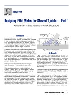
3 Forperpendicular Loading , = 90 , and the parenthetical termbecomes , permitting the increased allowable unit ExampleFigure 1. Lap joint with Fillet welds loaded in the two assemblies shown in Figures 1 and weld sizes would be computed as follows:Using an E70 electrode (E48), and with L = 4 (100mm, ), what weld size is needed to resist the applied loadof 40 kips (180 kN)?Welding Innovation Vol. XV, No. 2, 1998 FV= FEXX(1 + )ENGLISHFV= (70 ksi) (1 + ) = 21 ksiF = FV(A) = FV(2 welds) (L) ( ) ( ) === Use 3/8 filletMETRICFV= (480 MPa) (1 + ) = 144 MPa == m ( )Use 10 mm filletFigure 2. Lap joint with Fillet welds loaded (70 ksi) (1 + ) = ksi == Use 1/4 filletMETRICFV= (480 MPa) (1 + ) = 216 MPa == m ( mm)Use 6 mm filletConsistent with expectations, the welds in Figure 2 are per-mitted to be decreased in this case, by two standardweld sizes.
4 The welds in Figure 2 require 55% less weldmetal than the welds in Figure Deformation CapacityAlong with the increase in strength of welds loaded perpen-dicular to their length, the researchers found a decrease inthe deformation capacity before failure. If significant post-yielding deformation capacity is desired, the assembly inFigure 1 would be preferred. Most engineered structuresare expected to remain elastic under design loads, so con-sideration of only the strength is generally , for structures that may be subject to overloadconditions where large amounts of plastic deformation thatprecede failure are desired, the designer may choose to ori-ent the welds parallel to the major applied ApplicationsIn order to capitalize upon the additional allowable stresscapacity, the designer must orient the welds so that theyare as nearly perpendicular to the applied load as that the equation permits the use of any value of ,even though the examples have shown the extremes of 0 and 90.
5 The increased deformation capacity of longitudinallyloaded Fillet welds may have some design advantages incertain applications. when this is the case, geometriesthat involve the application of loads perpendicular to theweld s longitudinal axis should be designer has the opportunity to review existingdesigns and determine whether weld sizes can bereduced. It is imperative, however, that this approach onlybe employed where previous designs were based uponaccurate assumptions and calculations. In many applica-tions, weld sizes have been modified over the years,increasing or decreasing in weld sizes based upon proto-type behavior or field experiences. Reduction of weld sizesunder these conditions would be though the particular product that is being designedmay not fall under the domain of the Code, theseprinciples apply and could be used on other types of weld -ed applications other than orientation of welds with respect to the primary appliedload significantly affects the weld metal allowable stress, as well as the overall deformation capacity.
6 The designershould Consider these factors in order to maximize perfor-mance while minimizing Structural Welding Code: , 1994, pp. 4, Structural Welding Code: , 1998, pp. 8, , M. and Quinn, B. Examination of Fillet weld Strength, Engineering Journal,Vol. 31, No. 3. AISC, 1994, pp. 98 - , L. and Kulak, G. Strength of Fillet Welds as a function of Directionof Load, Welding Journal, Vol. 50, No. 5, 1971, The American WeldingSociety Research Supplement, pp. and Resistance Factor Design Specification for Structural SteelBuildings. AISC, 1993, pp. 6-77 and , G. and Kennedy, D. Behavior of Fillet Welds as a Function ofAngle of Loading , Canadian Journal of Civil Engineering, Vol. 15, 1989,pp. ( )40 kips(21 ksi)(2)(4 )( )40 kips( ksi)(2)(4 )( )180 kN(144 MPa)(2)( m)( )180 kN(216 MPa)(2)( m)( )