Transcription of Consideration of Slenderness Effect in Columns
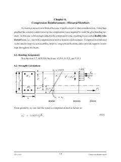
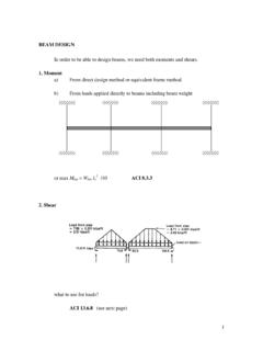
1 1 Consideration of Slenderness Effect in Columns Read Assignment Text: Section ; Code and Commentary: , General Short Column - Strength can be computed by considering only the column section properties. Slender Column - One whose strength is less than that computed based on section properties; axial load and moment capacities are significantly affected by length, loading conditions of column Concentrically Loaded Columns Euler postulated the phenomenon of elastic buckling as: 2222()(/)tcrtcrEIPKLEIfKL r == where Pcr = Maximum possible axial load Et = Tangent modulus of column material at buckling I = Moment of inertia of the section K = A scalar to adjust for column end conditions L = Column unsupported length r = Radius of gyration of section/rIA= Buckling Load Versus Slenderness Ratio: Figure 1.
2 Effect of Slenderness on Strength of Axially Load Column. 2If the stress-strain curve of short piece of the given member is of the shape of (a) below, as it would be for reinforced concrete Columns , Et is equal to Young s modulus, provided the buckling stress Pc/A is below the proportional limit If it is larger than fp, buckling occurs in the inelastic range. In this case Et is the tangent modulus (the slope of the stress-strain curve). As the stress increases Et decreases. A plot of the buckling load vs. the Slenderness ratio, a so-called column curve (Figure above), which shows the reduction in buckling strength with increasing Slenderness . If the Slenderness ratio is smaller than (kl/r)min failure occurs by crushing.
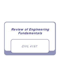
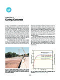
3 If the Slenderness ratio is larger than (kl/r)min failure occurs by buckling, buckling load or stress decreasing for greater Slenderness . 3 Evaluation of the "k" Coefficient Figure 2. Buckling and Effective Length of Axially Loaded Columns . Comments on Axially Loaded Columns A column might be considered short under some load conditions and end conditions, slender under others. Columns braced against side sway have effective length between and L. Columns not braced against side sway always have effective lengths greater than L. High strength steel and concrete make slender Columns more common. Consideration of length effects becomes more important. Evaluation of k will be considered in more detail in the next section.
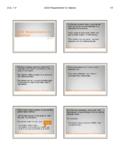
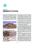
4 4In reinforced concrete structures we are not usually concerned with single members but rather with rigid frames of various configurations. See Figure 3, if sided say is prevented as indicated by a brace, the buckling configuration will be as shown in Figure The buckled shape of the column corresponds to Figure , except the lower end is hinged. The unbraced length kl will be smaller than l. On the other hand if no sides way bracing is provided to to an identical frame, the buckling will look like Figure The column is in a situation similar to that of upside down, except that the upper end is not fixed but only partially restrained by the girder. Even though both frames in Figure 3 are identical, the unbraced frame will buckle at a radically smaller load than the braced frame.
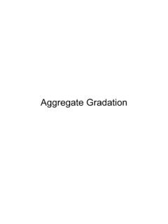
5 Figure 3. Rigid Frame Bucklin: (a) Laterally Braced; (b) unbraced. 5 Consideration of Second-Order Effects - Axial Load and Bending A column under the influence of axial load and bending will have a deformation at midspan (and in addition a maximum moment) which will be affected by the length and stiffness of the column (or "beam-column" as it may approximately be called). Consider a column bent in single curvature by either end moments or lateral loads: Figure 4. Moments in Slender Members with Compression plus Bending, Bent in Single Curvature. Is there a method by which the influence of axial load may be related to original deflection? It has been shown by Timoshenko and Gere that 011/cryypp= Where y = Elastic deflection of beam-column, single curvature yo = Deflection of corresponding beam without axial load P = Applied axial load Pcr = The critical axial load for the column without exterior moment 6 Johnson showed that with simplified assumptions, the maximum moment for the beam column could be written as max011/crMMpp= where Mmax = Maximum moment in the singly curved beam-column Mo = Maximum moment in beam, axial load where 1/(1 - P/Pcr)
6 Is known as a moment magnification factor, which reflects the amount by which the beam moment Mo is magnified by the presence of a simultaneous axial force P. Implications As Slenderness ratio increases, Pcr decreases and Mmax increases Figure 5. Effect of Slenderness and Effect of Axial Load on Column Moments. Keep in mind that our interaction diagram, derived earlier for a section is valid regardless of column length. We must reconsider its use in light of these modifications to load condition. Thus, we see high moment magnification in Columns with single curvature. What would occur in the case of column with end moments of opposite sense? 7 Resulting in Double Curvature.
7 Moment Diagram may take one of the following general shapes with maximum moments at or near ends: Figure 6. Moments in Slender Members with Compression Plus Bending, Bent in Double Curvature. As a result, our moment modification is small. The general moment magnification case may then be written as: max01/mcrcMMpp= where Cm = a factor of moment diagram relation + members braced against side sway no transverse loading = side sway, other cases. 8 M2 is the larger moment: 12MM is positive if have single curvature 12MM is negative if have double curvature Figure 7. Fixed Portal Frame, Laterally Unbraced. Figure 8. Fixed Portal Frame, Laterally Braced.
8 9 ACI Read. (a) Modulus of Elasticity ACI (b) Moment of Inertia Beams .. Columns .. Walls Cracked .. Flat Plates and Flat (c) Area ACI Radius of gyration for rectangular members, where h is in the direction stability is being considered, or circular members, where D is the diameter of the compression member. How do we find the column rigidity EI? Due to the fact that a reinforced column is a non-homogeneous member consisting of steel and concrete and concrete is subjected to creep and shrinkage while steel is not, it is not easy to find EI exactly. If we try to do an exact analysis to find the EI, the value we find will be as good as our assumptions.
9 ACI Section say: IEI +=+ ACI 10-11 page 128 Or conservatively =+ ACI 10-12 page 128 Where Ec = Modulus of elasticity of concrete, psi Es = Modulus of elasticity of steel, (29,000,000 psi) Ig = Moment of inertia of gross section (in4) Is = Moment of inertia of reinforcement about the centroidal axis of member cross section (in4) d = Ratio of maximum factored dead load moment to maximum factored total load moment, always positive.
10 10factor d accounts for the Effect of creep in the concrete. Therefore, it is more appropriate to apply the term 1+ d to the term EcIg/5 only because concrete is the one which creeps. Eq. 10-12 is not unreasonable for lightly reinforced concrete members, but greatly underestimates the Effect of reinforcement of heavily reinforced members. ACI CODE Consideration OF LENGTH EFFECTS IN Columns A. Braced Frames. For moment resisting frame that is effectively braced against sides way by shear walls or diagonally braced frames: 2cnsMM = ACI 10-8 where the moment-magnification factor is given as: = ACI 10-9 22()tcruEIPkl = ACI 10-10 where lu is the unsupported length of compression member For the frames braced against side sway and without loads between supports (ACI 318 Sect.)