Transcription of Considerations for Instrument Grounding - Keysight
1 TECHNICAL OVERVIEWC onsiderations for Instrument GroundingPage 2 Find us at Many people have heard of the term " Grounding ", but few fully understand its meaning and importance. Sometimes, even experienced electricians do not treat Grounding as a serious issue. The impact of an incorrect or absent Grounding ranges from noise interference. resonance or humming during the use of electrical equipment to the worst case where electricity leakage through the chassis causes personal injury or damage to Instrument components. Grounding , therefore, is a very practical issue that should be dealt with properly. For those who operate electrical equipment frequently, a complete understanding of Grounding theories and applications is necessary in order to become a best-in-class the eighteenth century, Benjamin Franklin performed the famous kite experiment to observe how lightning in the sky was conducted to the earth. This experiment led to the invention of lightning rods to avoid lightning strikes.
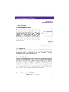
2 From then on, people began to realize that the vast ground under our feet is a huge electrical conductor. It may not be the best conductor, but it is certainly a good one. It is so enormous in size that it can sustain a tremendous amount of current. That is why the voltage level of the ground is set to be zero. Safety regulations require that all metal parts which do not carry electricity should be kept at zero or the earth voltage are several reasons for Grounding . Some are for safety purposes, and some are for maintaining circuit stability. The following are some examples: Power system Grounding : As you can see in Figure 1. this design is to prevent the secondary side from being damaged by the high voltage on the primary side, as the current will be conducted to the ground through the Grounding Wire to protect human lives. Instrument Grounding : By connecting the equipment or chassis to the ground, operators can be protected from electric shocks if there is electricity leakage. Signal Grounding : A zero voltage reference or a loop-back path is provided for all integrated signals to ensure proper operation or accurate measurements.
3 Shielded Grounding : This is used to prevent static electricity from being accumulated. Ground isolation or conduction can help to reduce noises and electro-magnetic interference. Examples include shielding rooms, cables, wirelines, guarded terminals of instruments , transformers and voltageGrounding wireGrounding electrodeEarth groundHigh voltagePrimaryPage 3 Find us at Types of Instrument GroundingFigure 2 shows a commonly used Instrument Grounding on inputs and AC power. In this case. the input signal ground is connected to the power ground and when you are making a measurement, it is important to make sure that the input signal ground is not short-circuited directly to any point where there is a voltage difference to the earth ground. This is very common when measuring commercially available low-cost circuits. To reduce costs, these circuits usually do not use power isolated transformers . Instead, the AC power is directly connected to the circuit. As a result. a loop is formed between the circuit itself and the earth ground, and a voltage difference occurs.
4 If the AC power happens to be plugged in the reverse way, or a considerable voltage difference exists between the neutral line and the earth ground, the combined factors could lead to very unpredictable results. Therefore, caution must be exercised before the input is connected for avoid the problem described above, some instruments provide floating inputs as shown in Figure 3. Each of the inputs is floating from the earth ground. Ideally, as long as the voltage difference between these two inputs is within an acceptable range, the inputs can be connected to any voltage 4(a) and 4(b) show some common instruments for output devices. For DC or low frequency generators, the design shown in 4(a) is usually adopted, while for high frequency (RF) generators, the model in 4(b) is used. Therefore, special attention is required to avoid the problem described in item (1) when performing a high frequency measurement. Otherwise, the voltage difference and conflict may cause damage to the input and output of Instrument caseAC plugSignal groundPower transformerInputSensingelectronics and display+ Instrument caseAC plugShieldgroundPower transformerInputSensingelectronics and display+ Instrument caseAC plugCase groundPower transformerOutputGenerating electronicsInstrument caseAC plugShield groundPower transformerOutputOutput conditioningelectronics(a)(b)Page 4 Find us at Guidelines for Instrument GroundingWhile there are some guidelines for Grounding , there is no hard and fast rule.
5 In practice, it is difficult to follow all the guidelines. Rather, it is dependent on the environment and applications. For instance, before the measurement is performed, evaluations should be made to decide whether the floating method should be used. The following are some general guidelines: When dealing with different kinds of Grounding such as shielded Grounding , power Grounding and signal Grounding , make sure that they are guided to their own paths to avoid interaction. Keep the impedance of the ground line low and the path short. Avoid multiple ground loops, which may disturb current flows. Isolate the heavily loaded ground current loop from the small signal s take a look at the example in Figure 5. For a well-designed power supply equipment. the voltage ripple between output A and B should be very small. However, if for convenience sake, point C instead of point D is used as the signal s ground reference, a significant pulse voltage will occur and show up on the output circuit even when the resistance between point C and D is small.
6 This is because the transient current in charging or discharging the capacitors is usually very high. As a result, as soon as the power is on, damage can be caused to the connected circuits or regulatorFigure 5 Find us at Common Causes of Poor GroundingThe AC power (such as 110 V) socket does not provide the ground line (green). as shown in Figure 6. The earth pole on the plug is usually the longest so that it can be connected to the ground first when the AG power cord is plugged into the actual impedance to the ground is too high which does not comply with electrical regulations (please refer to the appropriate regulations in your country). Take the example of the third level regulation of Grounding . When the AG voltage to the ground is above 300 V. the impedance to the ground must be less than 10 . If the AG voltage to the ground is under 150 V. the impedance to the ground should be within 100 .The neutral line is mistakenly used as the ground line and these two lines are short-circuited together on the socket.
7 Under normal conditions, the voltage difference between the neutral line and the ground line on the socket must be within V, but this should not be accomplished by short-circuiting these two lines the hot line and the neutral line arbitrarily. Take Figure 7 as an example. Equipment A sends out signals while equipment B receives signals. Suppose the AG power sockets to which Equipment A and B are connected do not provide the ground line. and the hot line and neutral line are swapped on one of the equipment. Since equipment A and B both have noise filters installed. a 110 V AG loop is therefore formed accidentally even when the power switch of A and B is not AEquipment BEarthEach pole in the figure represents:L: Line, hot or active conductorN: Neutral or identified conductorG: Ground or earth conductorNLG5-15 RPage 6 Find us at SummaryWhen installing the equipment in a building, make sure to have an electrician check on the impedance to the ground and the Grounding device to see if they comply with electrical regulations.
8 8 AWG wireline should be used as a minimum wire type for Instrument the three-pole AC power socket for the Instrument . Make sure the polarity of the hot line and the neutral line is correct (see Figure 6). The voltage difference between the neutral and the ground lines should be less than 1 V. At the socket end. the impedance between the neutral and the ground lines should be lower than 1 .Find out the appropriate way to do measurements. whether the Instrument 's input/output terminals should be grounded or be the stability of the AC power (ex. +5% to 10% within 120 V) and whether there are unpredictable impulses, which may cause the measurement to fail or even damage the Instrument . Generally, the transient voltage fluctuation should not exceed 15% within 120 V and the voltage should be restored to 120 V within second. The total harmonic component should be less than 5%.Verify the Grounding of the equipment or device under test (OUT). If voltage differences exist among equipment, connecting them together may cause conflicting situations.
9 The sudden pulses generated when the equipment is powered on may also damage vulnerable modules. If this happens, the links between the equipment and devices under test should be disconnected before the AC power is turned on. Each equipment and OUT should be reconnected only after all equipment and devices have stabilized. In so doing, the possibilities of damage can be minimized. However, this is not the way to eradicate the problem completely. The best solution is to identify the root causes and fix and remove unwanted static, interference and noise through proper Test and Measurement Service Centers have been providing comprehensive and precise repair and calibration services to customers for many years. Our pursuit of quality and technical innovation enables us to offer better services to our customers. By sharing this article with you, we hope to help you improve the accuracy of measurements and the life span of your 7 Find us at Appendix 1: AC Power Control PanelIn most countries, electric power companies will provide building occupants AC power electricity with a Y connection configuration (Figure 8), which offers three live/hot lines (a), (b), (c) and one neutral line that is colored white.
10 This configuration is called a 3-phase 4-wire AC power system. The voltage between either one of the live lines and the neutral line is about 108 to 126 V, while the voltage between the two live lines is about 187 to 218 V. The neutral line inside the AC power transformer is connected to earth, which in the event of an AC power transformer failure bypasses a potentially damaged current into the ground, thus preventing any damage to the occupant s equipment. This neutral line also performs as a reference point for balancing three phase should provide one independent Grounding line (G) colored green, with a resistance of about 1 , connected to the AC power control panel. It is not the responsibility of the electric power company to provide this. In many cases, either the builder or the occupant may overlook this step, resulting in a missing Grounding wire, or the neutral line being mis-used as the ground neutral line (N) should not be used as the ground line. The key concern is that the dynamic loading current.