Transcription of Constant-Current 3-Ampere PWM Dimmable Buck …
1 The A6211 is a single IC switching regulator that provides Constant-Current output to drive high-power LEDs. It integrates a high-side N-channel DMOS switch for DC-to-DC step- down ( buck ) conversion. A true average current is output using a cycle-by-cycle, controlled on-time method. Output current is user-selectable by an external current sense resistor. Output voltage is automatically adjusted to drive various numbers of LEDs in a single string. This ensures the optimal system dimming is accomplished by a direct logic input pulse-width modulation (PWM) signal at the enable device is provided in a compact 8-pin narrow SOIC package (suffix LJ) with exposed pad for enhanced thermal dissipation. It is lead (Pb) free, with 100% matte-tin leadframe , Rev. 5 Supply voltage 6 to 48 V True average output current control 3 A maximum output over operating temperature range Cycle-by-cycle current limit Integrated MOSFET switch Dimming via direct logic input or power supply voltage Internal control loop compensation Undervoltage lockout (UVLO) and thermal shutdown protection Low power shutdown (1 A typical) Robust protection against: Adjacent pin-to-pin short Pin-to-GND short Component open/short faults Constant-Current 3-Ampere PWM Dimmable buck Regulator LED DriverPackage: 8-pin SOICN with exposed ther-mal pad (suffix LJ):APPLICATIONS.
2 General illumination Scanners and multifunction printers (light bars) Architectural lighting Industrial lighting Display case lighting / MR16 Typical Application CircuitNot to scaleA6211C1R1 GNDVINVIN (6 to 48 V)12348765 SWGNDPADVCCA6211 BOOTTONENCSC5C4D1L1 LED+LED RSENSEENE nable/PWM Dimming(100 Hz to 2 kHz).. FEATURES AND BENEFITSDESCRIPTIONC onstant-Current 3-Ampere PWM Dimmable buck Regulator LED DriverA62112 Allegro MicroSystems, LLC115 Northeast CutoffWorcester, Massachusetts 01615-0036 ; Maximum RatingsCharacteristicSymbolNotesRatingUn itSupply Voltage VIN to 50 VBootstrap Drive VoltageVBOOT to VIN + 8 VSwitching VoltageVSW to VIN + Regulator TerminalVCCVCC to GND to 7 VEnable and TON VoltageVEN , VTON to VIN + Sense VoltageVCS to 7 VOperating Ambient TemperatureTAG temperature range 40 to 105 CMaximum Junction TemperatureTJ(max)150 CStorage TemperatureTstg 55 to 150 CSelection GuidePart NumberOperating Ambient Temperature, TAPackagePackingA6211 GLJTR-T 40 C to 105 C8-pin SOICN with exposed thermal pad3000 pieces per 13-in reelPinout DiagramTerminal List TableNumberNameFunction1 VINS upply voltage input terminals2 TONR egulator on-time setting resistor terminal3 ENLogic input for Enable and PWM dimming4 CSDrive output current sense feedback5 VCCI nternal linear regulator output6 GNDG round terminal7 BOOTDMOS gate driver bootstrap terminal8 SWSwitched output terminals PADE xposed pad for enhanced thermal dissipation; connect to GNDSWBOOTGNDVCCVINTONENCS12348765 PADT hermal Characteristics*: may require derating at maximum conditions.
3 See application section for optimizationCharacteristicSymbolTest Conditions*ValueUnitPackage Thermal Resistance (Junction to Ambient)R JAOn 4-layer PCB based on JEDEC standard35 C/WOn 2-layer generic test PCB with of copper area each side62 C/WPackage Thermal Resistance (Junction to Pad)R JP2 C/W*Additional thermal information available on the Allegro 3-Ampere PWM Dimmable buck Regulator LED DriverA62113 Allegro MicroSystems, LLC115 Northeast CutoffWorcester, Massachusetts 01615-0036 ; + + + VIL = VVIH = VBOOTCVCCCBOOTL1D1 LED StringVCCS hutdownVINVINCCOMPENTONRONCSGNDRSENSESWO n-TimeCurrentGeneratorOn-TimeTimerIC and DriverControl LogicLevel ShiftGate Drive UVLOVCCUVLOOff-TimeTimerVREG V+ buck Switch Current SenseCurrent LimitOff-TimeTimerILIMT hermalShutdownVCC UVLOPADA verageFunctional Block DiagramConstant-Current 3-Ampere PWM Dimmable buck Regulator LED DriverA62114 Allegro MicroSystems, LLC115 Northeast CutoffWorcester, Massachusetts 01615-0036.
4 Supply VoltageVINTA = 25 C6 48 VVIN Undervoltage Lockout ThresholdVUVLOVIN increasing VVIN Undervoltage Lockout HysteresisVUVLO_HYSVIN decreasing 150 mVVIN Pin Supply CurrentIINVCS = V, EN = high 5 mAVIN Pin Shutdown CurrentIINSDEN shorted to GND 110 ABuck Switch Current Limit Switch On-ResistanceRDS(on)VBOOT = VIN + V, TA = 25 C, ISW = 1 A BOOT Undervoltage Lockout ThresholdVBOOTUVVBOOT to VSW BOOT Undervoltage Lockout HysteresisVBOTUVHYSVBOOT to VSW decreasing 370 mVSwitching Minimum Off-TimetOFFminVCS = 0 V 110150nsSwitching Minimum On-TImetONmin 110150nsSelected On-TimetONVIN = 24 V, VOUT = 12 V, RON = 137 k 80010001200nsRegulation Comparator and Error AmplifierLoad Current Sense Regulation Threshold 1 VCSREGVCS decreasing, SW turns Current Sense Bias CurrentICSBIASVCS = V, EN = low AInternal Linear RegulatorVCC Regulated OutputVCC0 mA < ICC < 5 mA, VIN > 6 Current Limit 2 ICCLIMVIN = 24 V, VCC = 0 V520 mAEnable InputLogic High VoltageVIHVEN VLogic Low VoltageVILVEN decreasing Pin Pull-down ResistanceRENPDVEN = 5 V 100 k Maximum PWM Dimming Off-TimetPWMLM easured while EN = low, during dimmingcontrol.
5 And internal references are powered-on(exceeding tPWML results in shutdown)1017 msThermal ShutdownThermal Shutdown ThresholdTSD 165 CThermal Shutdown HysteresisTSDHYS 25 C1 In test mode, a ramp signal is applied at CS pin to determine the CS pin regulation threshold voltage. In actual application, the average CS pin voltage is regulated at VCSREG regardless of ripple The internal linear regulator is not designed to drive an external loadELECTRICAL CHARACTERISTICS: Valid at VIN = 24 V, for TA = 40 C to 105 C, typical values at TA = 25 C, unless otherwise notedConstant-Current 3-Ampere PWM Dimmable buck Regulator LED DriverA62115 Allegro MicroSystems, LLC115 Northeast CutoffWorcester, Massachusetts 01615-0036 ; PERFORMANCEP anel 1B. VIN = 24 VPanel 1C. VIN = 30 VPanel 1A. VIN = 19 VtC1,C2C3C4 VINVOUTiLEDVENF igure 1: Startup waveforms from off-state at various input voltages; note that the rise time of the LED current depends on input/output voltages, inductor value, and switching frequency Operating conditions: LED voltage = 15 V, LED current = A, R1 = k (frequency = 1 MHz in steady state), VIN = 19 V (panel 1A), 24 V (panel 1B) and 30 V (panel 1C) Oscilloscope settings: CH1 (Red) = VIN (10 V/div), CH2 (Blue) = VOUT (10 V/div), CH3 (Green) = iLED (500 mA/div), CH4 (Yellow) = Enable (5 V/div), time scale = 50 s/divtC1,C2C3C4 VINVOUTiLEDVENtC1,C2C3C4 VINVOUTiLEDVENC onstant-Current 3-Ampere PWM Dimmable buck Regulator LED DriverA62116 Allegro MicroSystems, LLC115 Northeast CutoffWorcester, Massachusetts 01615-0036 ; 2: PWM operation at various duty cycles.
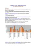
6 Note that there is no startup delay during PWM dimming opera-tion Operating conditions: at 200 Hz, VIN = 24 V, VOUT = 15 V, R1 = k , duty cycle = 50% (panel 2A) and 2% (panel 2B) CH1 (Red) = VIN (10 V/div), CH2 (Blue) = VOUT (10 V/div), CH3 (Green) = iLED (500 mA/div), CH4 (Yellow) = Enable (5 V/div), time scale = 1 ms/div (panel 2A) and 50 s/div (panel 2B) Panel 2A: Duty cycle = 50% and time scale = 1 ms/divPanel 2B: Duty cycle = 2% and time scale = 50 s/divC1,C2C1,C2C3C3C4C4 VINVINVOUTVOUTiLEDiLEDVENVENC onstant-Current 3-Ampere PWM Dimmable buck Regulator LED DriverA62117 Allegro MicroSystems, LLC115 Northeast CutoffWorcester, Massachusetts 01615-0036 ; , (%)LED Current, iLED (A)VIN = 24 V, VOUT = 15 VVIN = 12 V, VOUT = VVIN = 12 V, VOUT = , (%)LED Current, iLED (A)fSW = 500 kHzfSW = 1 MHzfSW = 2 Cycle (%)LED Current (A)iLED = 3 AiLED = 2 AiLED = AFigure 3: Efficiency versus LED Current at various LED voltages Operating conditions: fSW = 1 MHzFigure 4: Efficiency versus LED Current at various switching frequencies.
7 Operating conditions: VIN = 12 V, VOUT = VFigure 5: Average LED Current versus PWM dimming percentage Operating conditions: VIN = 12 V, VOUT = V, fSW = 1 MHz, fPWM = 200 Hz, L = 10 HConstant-Current 3-Ampere PWM Dimmable buck Regulator LED DriverA62118 Allegro MicroSystems, LLC115 Northeast CutoffWorcester, Massachusetts 01615-0036 ; A6211 is a buck regulator designed for driving a high-current LED string. It utilizes average current mode control to maintain constant LED current and consistent brightness. The LED current level is easily programmable by selection of an external sense resistor, with a value determined as follows:iLED = VCSREG / RSENSE where VCSREG = V FrequencyThe A6211 operates in fixed on-time mode during switching. The on-time (and hence switching frequency) is programmed using an external resistor connected between the VIN and TON pins, as given by the following equation:tON = k (RON + RINT ) ( VOUT / VIN )fSW = 1 / [ k (RON + RINT )]where k = , with fSW in MHz, tON in s, and RON and RINT (internal resistance, 5 k ) in k (see Figure 6).
8 Enable and DimmingThe IC is activated when a logic high signal is applied to the EN (enable) pin. The buck converter ramps up the LED current to a target level set by RSENSE. When the EN pin is forced from high to low, the buck converter is turned off, but the IC remains in standby mode for up to 10 ms. If EN goes high again within this period, the LED current is turned on immediately. Active dimming of the LED is achieved by sending a PWM (pulse-width modulation) signal to the EN pin. The resulting LED brightness is proportional to the duty cycle (tON / Period ) of the PWM signal. A practical range for PWM dim-ming frequency is between 100 Hz (Period = 10 ms) and 2 kHz. At a 200 Hz PWM frequency, the dimming duty cycle can be varied from 100% down to 1% or EN is low for more than 17 ms, the IC enters shutdown mode to reduce power consumption. The next high signal on EN will initialize a full startup sequence, which includes a startup delay of approximately 130 s.
9 This startup delay is not present during PWM EN pin is high-voltage tolerant and can be directly connected to a power supply. However, if EN is higher than the VIN voltage at any time, a series resistor (1 k ) is required to limit the current FUCNTIONAL DESCRIPTIONF igure 6: Switching Frequency versus RTON Resistance Figure 7: Simplified buck Controller Equations, and Reference Circuit and Waveforms 100 120 140 160 180 200 220 240 260fsw (MHz)RTON (k ) During SW on-time:iRIPPLE = [(VIN VOUT) / L] tON = [(VIN VOUT) / L] T DiRIPPLE = [(VOUT VD) / L] tOFF = [(VOUT VD) / L] T (1 D)VOUT = VIN D VD (1 D)VOUT = (VIN Iav RDS(on) ) D VD (1 D) RL Iavwhere D = tON / RL is the resistance of the inductor. During SW off-time:Therefore (simplified equation for Output Voltage):More precisely:If VD << VOUT , then VOUT VIN (max)iavi(min)0iRIPPLEtONtOFFT VDCINVINA6211 SWVOUTRSENSELiLMOSDC onstant-Current 3-Ampere PWM Dimmable buck Regulator LED DriverA62119 Allegro MicroSystems, LLC115 Northeast CutoffWorcester, Massachusetts 01615-0036 ; into the EN pin.
10 This series resistor is not necessary if EN is driven from a logic Dimming RatioThe brightness of the LED string can be reduced by adjusting the PWM duty cycle at the EN pin as follows: Dimming ratio = PWM on-time / PWM periodFor example, by selecting a PWM period of 5 ms (200 Hz PWM frequency) and a PWM on-time of 50 s, a dimming ratio of 1% can be an actual application, the minimum dimming ratio is deter-mined by various system parameters, including: VIN , VOUT , inductance, LED current, switching frequency, and PWM frequency. As a general guideline, the minimum PWM on-time should be kept at 50 s or longer. A shorter PWM on-time is acceptable under more favorable operating Voltage and Duty CycleFigure 7 provides simplified equations for approximating output voltage. Essentially, the output voltage of a buck converter is approximately given as:VOUT = VIN D VD1 (1 D ) VIN D, if VD1<< VIND = tON / (tON + tOFF )where D is the duty cycle, and VD1 is the forward drop of the Schottky diode D1 (typically under V).