Transcription of CONTAINS TWO SEPARATE AUDIO SYSTEMS - Elenco
1 AM/FM RADIO KITMODEL AM/FM-108CK SUPERHET RADIOCONTAINS TWO SEPARATE AUDIO SYSTEMS :IC AND TRANSISTORELENCO Copyright 2012 by Elenco All rights reserved. 753510No part of this book shall be reproduced by any means; electronic, photocopying, or otherwise without written permission from the and Instruction Manual-1-The AM/FM Radio project is divided into two parts, the AM Radio Section and the FM Radio Section. At thistime, only identify the parts that you will need for the AM radio as listed below. DO NOT OPEN the bags listedfor the FM radio. A SEPARATE parts list will be shown for the FM radio after you have completed the AM LIST FOR THE AM RADIO SECTIONIf you are a student, and any parts are missing or damaged, please see instructor or you purchased this kit from a distributor, catalog, etc.
2 , please contact Elenco (address/phone/e-mail is atthe back of this manual) for additional assistance, if needed. DO NOTcontact your place of purchase as theywill not be able to help CodePart #r1R4510 5% 1/4 Wbrown-black-black-gold121000r2R44, 4847 5% 1/4 Wyellow-violet-black-gold124700r4R38, 43, 50, 51100 5% 1/4 Wbrown-black-brown-gold131000r1R49330 5% 1/4 Worange-orange-brown-gold133300r1R41470 5% 1/4 Wyellow-violet-brown-gold134700r1R371k 5% 1 5% 1/4 Wred-red-red-gold142200r3R33, 36, 5% 1/4 Worange-orange-red-gold143300r1R4010k 5% 1/4 Wbrown-black-orange-gold151000r1R3212k 5% 1/4 Wbrown-red-orange-gold151200r1R3527k 5% 1/4 Wred-violet-orange-gold152700r1R3939k 5% 1/4 Worange-white-orange-gold153900r1R3156k 5% 1/4 Wgreen-blue-orange-gold155600r1R47470k 5% 1/4 Wyellow-violet-yellow-gold164700r1R341M 5% 1/4 Wbrown-black-green-gold171000r1 Volume/S250k / SWPotentiometer / switch with nut and plastic #r1C30150pFDiscap (151) F Discap (102)244780r2C31, F Discap (103)241031r5C29, 33, 35, 36, F or F Discap (203) or (223) F Discap (473)
3 244780r2C28, F Discap (104)251010r4C32, 40, 41, 4210 F Electrolytic radial (Lytic)271045r1C4747 F Electrolytic radial (Lytic)274744r1C34100 F Electrolytic radial (Lytic)281044r2C39, 43470 F Electrolytic radial (Lytic)284744r1C1 VariableTuning gang #r2D4, 51N4148 Diode314148r5Q7, 8, 9, 10, 112N3904 Transistor NPN323904r1Q122N3906 Transistor PNP323906r1Q14JE8050 Transistor NPN328050r1Q13JE8550 Transistor PNP328550r1U1LM386 Integrated circuit330386 COILSMAGIC # #r1L5 RedAM oscillator430057r1 Iron core461000r1T6 YellowAM IF430260r1 Brass core661150r1T7 WhiteAM IF430262r4 Shrink tubing890120r1T8 BlackAM IF430264r1L4AM antenna with holders484004-2-PARTS LIST FOR THE AM RADIO SECTION (continued)MISCELLANEOUS** SAVE THE BOX THAT THIS KIT CAME IN.
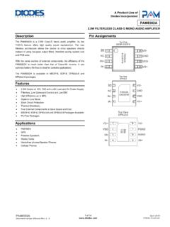
4 IT WILL BE USED ON PAGES 32 & 61. ** #r1PC board, transistor AUDIO amplifier510007r1PC board, main517055r1 Switch541023r1 Battery holder590096r1 Speaker590102r2 Header male 4-pin591004r1 Speaker pad780128r1 Knob (dial)622040r1 Knob (pot)622050r1 Earphone jack with nut622130r1 Radio #r1 Earphone629250r3 Screw x (battery holder)641100r1 Screw x (dial)641107r2 Screw x (gang)641310r3 Nut washer645108r1 Socket 8-pin664008r12 Test point pin665008r1 Label AM/FM723059r8 Wire 22 AWG insulated814520r1 Solder lead-free9LF99 PARTS IDENTIFICATIONRESISTORSCAPACITORSSEMICON DUCTORSC arbon filmDiscapElectrolytic radialTuning gangAM/FMDiodeTransistorAntenna AssemblyCoilColor dotEarphone jackwith nutKnob (dial)Radio standCOILSMISCELLANEOUSL abel AM/FMScrew x x pad50k Potentiometer / switchwith nut, metal washer,and plastic washerKnob(pot)Screw x holdersFerrite core8-pin SocketLM386 ICSlide switchBattery holderSpeakerEarphoneHardwareHeader male 4-pinNote:The following parts are used in the Transistor AUDIO amplifier Section (packaged in a SEPARATE bag) R46, R47, R48, R49, R50,R51, C46, C47, D5, Q10, Q11, Q12, Q13, Q14, PC board (transistor AUDIO amplifier ), test point pin (qty.)
5 4), and header male 4-pin (qty. 2).Brass coreIron coreShrink tubingTest point pin-3-Warning:If the capacitor isconnected withincorrect polarity, itmay heat up andeither leak, orcause the capacitorto RESISTOR VALUESUse the following information as a guide in properly identifying the value of UNITS AND CONVERSIONSA bbreviationMeansMultiply Unit unit1100kkilo1,000103 Mmega1,000,0001061. 1,000 pico units= 1 nano unit2. 1,000 nano units= 1 micro unit3. 1,000 micro units = 1 milli unit4. 1,000 milli units= 1 unit5. 1,000 units= 1 kilo unit6. 1,000 kilo units= 1 mega unitIDENTIFYING CAPACITOR VALUESC apacitors will be identified by their capacitance value in pF (picofarads), nF (nanofarads), or F (microfarads).Most capacitors will have their actual value printed on them.
6 Some capacitors may have their value printed inthe following manner. The maximum operating voltage may also be printed on the DigitFirst DigitMultiplierTolerance*Note: The letter R may be used at timesto signify a decimalpoint; as in 3R3 = letter M indicates a tolerance of +20%The letter K indicates a tolerance of +10%The letter J indicates a tolerance of +5%Maximum Working VoltageThe value is 10 x 1,000 =10,000pF or .01 F 100V*Electrolytic capacitors have a positiveand a negative electrode. Thenegative lead is indicated on thepackaging by a stripe with minussigns and possibly arrowheads. Also,the negative lead of a radialelectrolytic is shorter than the 11st DigitColorDigitBlack0 Brown1 Red2 Orange3 Yellow4 Green5 Blue6 Violet7 Gray8 White9 BAND 22nd DigitColorDigitBlack0 Brown1 Red2 Orange3 Yellow4 Green5 Blue6 Violet7 Gray8 White9 MultiplierColorMultiplierBlack1 Brown10 Red100 Orange1,000 Yellow10,000 Green100,000 Blue1,000, 10%Gold 5%Brown 1%Red 2%Orange 3%Green the (+)( )(+)( )
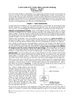
7 AxialRadialSection 9-4-FM RFAMPLIFIERFMOSCILLATOR1ST FM IFAMPLIFIERAFCF igure 1 Section 8 Section 7 Section 6 Section 1 Section 5 Section 4 Section 3 Section 2FM MIXER2ND FM IFAMPLIFIERFMDETECTORAM MIXERAMOSCILLATOR1ST AM IFAMPLIFIER2ND AM IFAMPLIFIERAMDETECTORAGCIC orTRANSISTORAUDIOAMPLIFIERS peakerFM RADIOAM RADIOThe purpose of Section 1, the AUDIO amplifier Stage, is toincrease the power of the AUDIO signal received from eitherdetector to a power level capable of driving the speaker. Theaudio amplifier is IC or transistor version. Section 2 includesthe AM detector circuit and the AGC (automatic gain control)stage. The AM detector converts the amplitude modulated IF(intermediate frequency) signal to a low level AUDIO AGC stage feeds back a DC voltage to the first AM IFamplifier in order to maintain a near constant level of AUDIO atthe detector.
8 Section 3 is the second AM IF amplifier . Thesecond AM IF amplifier is tuned to 455kHz (Kilohertz) andhas a fixed gain at this frequency of 50. Section 4 is the firstAM IF 2 amplifier which has a variable gain that depends onthe AGC voltage received from the AGC stage. The first AMIF amplifier is also tuned to 455kHz. Section 5 includes theAM mixer, AM oscillator and AM antenna stages. When theradio wave passes through the antenna, it induces a smallvoltage across the antenna coil. This voltage is coupled to themixer, or converter, stage to be changed to a frequency of455kHz. This change is accomplished by mixing(heterodyning) the radio frequency signal with the oscillatorsignal.
9 Section 6 is the FM ratio detector circuit. The FM ratiodetector has a fixed gain of about 20. Section 7 is the secondFM IF amplifier . The second FM IF amplifier is tuned (Megahertz) and has a set gain of approximately20. The 3dB bandwidth of this stage should be approximately350kHz. Section 8 is the first FM IF amplifier . The first FM IFamplifier is also tuned to and has a set gain ofapproximately 10. It also has a 3dB bandwidth of 9 includes the FM mixer, FM oscillator, FM RF (RadioFrequency) amplifier , AFC (Automatic Frequency Control)stage, and the FM antenna. The incoming radio waves areamplified by the FM RF amplifier , which is tuned to a desiredradio station in the FM frequency bandwidth of 88 MHz to108 MHz.
10 These amplified signals are then coupled to the FMmixer stage to be changed to a frequency of Thischange, as in AM, is accomplished by heterodyning the radiofrequency signal with the oscillator signal. The AFC stagefeeds back a DC voltage to the FM oscillator to prevent theoscillator from drifting. Each of these blocks will be explainedin detail in the Theory of Operation given before the assemblyinstructions for that DISCUSSIONINTRODUCTIONThe Elenco Superhet 108C AM/FM Radio Kit is a superheterodyne receiver of the standard AM (amplitudemodulation) and FM (frequency modulation) broadcastfrequencies. The unique design of the Superhet 108 allowsyou to place the parts over their corresponding symbol in theschematic drawing on the surface of the printed circuit boardduring assembly.