Transcription of CONTENTS 1 General Information 5 - Digimess Instruments
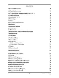
1 CONTENTS 1 General Information 5 Safety Instructions 5 Measuring Conditions 5 Switching the Operating Voltage 230 V~/115 V~ 6 Mains Connection 6 Installing the RLC 300 6 Switching on 7 EMC 7 Inspection and Maintenance 7 Warranty 7 Accessories Supplied 7 2 Application 9 3 Configuration and Functional Description 10 Block Diagram 10 Description 11 4 Technical Data 12 General Data 12 Specifications 12 Measuring Functions 12 Operating Parameters 13 Measuring Signal Parameters 13 Measuring Ranges 14 Measuring Accuracy 14 Measuring Errors during /Z/, R, L.
2 C Measurement 14 Measuring Errors during D Measurement 15 Measuring Errors during Q Measurement 15 Measuring Errors during Measurement 15 Additional Errors and Coefficients 16 Display 17 System Interfaces 17 Interface GPIB 17 Interface RS-232C 17 Plug Connections of Cable 18 5 Instrument Setting 19 Connection of the Measured Objects 19 Control Elements 20 1 Operating Instructions RLC 3001/99 Starting 22 6 Operation of the RLC 300 24 Introduction 24 Measuring Signal Parameters 24 Frequency of the Measuring Signal 24 Setting the Frequency 24 Level of the Measuring Signal 25 Setting the Level 25 Polarization Voltage 26 Setting the Polarization Voltage 26 Measuring Functions 27 Automatic Measurement of the Main Parameters 27 Performing the Automatic Measurement 27 Specific Measurement of the Impedance Parameters 28 Performing the Specific Measurement 28 Tolerance Measurement 29 Input of Reference and Limiting Values 29 Performing the Tolerance Measurement 33 Operating Parameters 36 Selection of the Equivalent Circuit of the Measured Object 36 Setting the Equivalent Circuit 37
3 Measuring Range Selection 37 Setting the Measuring Range 38 Error Messages 38 Residual Parameters of the Measuring Terminals 39 Measuring the Residual Parameters 40 Correcting the Residual Parameters 41 Trigger Function 41 Setting the Trigger Mode 42 Averaging Function 42 Switching on/off the Averaging Function 43 Additional Functions 44 Monitor Function 44 Measuring and Displaying the Measuring Signal Parameters 44 Measuring and Displaying the Polarization Voltage 45 User Functions 45 Saving the Current Instrument Settings 45 Loading the Saved Instrument Setting 47 Switching on/off the Initialization Test 47 Settings at the Display 48 Service Functions 49 Self-diagnosis of the RLC 300 50 Special Functions of the RLC 300 50 7 Remote Control by Program 51 Remote Control via GPIB (IEEE )
4 51 Connection of the RLC 300 to the System 51 2 Operating Instructions RLC 300 1/99 Selection of the Interface Type 51 Interface Parameters 52 Setting the GPIB Address 52 Operation without Control Unit - TON 52 Remote Control via RS-232C 53 Connection of the RLC 300 to the PC 53 Selection of the Interface Type 53 Interface Parameters 53 Setting the Baud Rate 54 Setting the Transmission Protocol 55 Transmission Protocol 55 Communication with RTS/CTS Protocol 55 Communication without RTS/CTS protocol 55 Local Control Remote Control 56 Messages of the RLC 300 on Remote Control 57 Description of the Unit Status 57 ESR - EVENT STATUS REGISTER 57 STB - STATUS BYTE REGISTER 58 Description of Errors 59 DER - DEVICE ERROR REGISTER 60 Error Messages 60 List of Commands on Remote Control 62 General Commands 62 Interface commands 62 Initializing the Instrument Settings 63 Self-Diagnosis of the RLC 300 63 Identification of the RLC 300 63 Initializing the Error Register 63 Synchronization Commands 63 Query of the Instrument Status 64 Instrument Settings and Messages 64 Frequency of the
5 Measuring Signal 64 Levels of the Measuring Signal 64 Polarization Voltage 65 Automatic Measurement of the Main Parameters 65 Specific Measurement of the Impedance Parameters 65 Automatic Selection of the Equivalent Circuit of the Measured Object 66 Manual Selection of the Equivalent Circuit of the Measured Object 66 Automatic Measuring Range Selection 66 Manual Measuring Range Selection 66 Residual Parameters of the Measuring Terminals 67 Monitor Function 67 Averaging function 67 Tolerance Measurement 67 Trigger Function 69 Saving and Loading of the Instrument Setting 69 Transmitting the Results 70 Measurement of the Main Parameters 70 Tolerance Measurement 70 3 Operating Instructions RLC 3001/99 Measuring Parameters at Active Monitor Function 71 Programming Notes 72 Program Examples (Q Basic) 73 Remote Control via Interface GPIB 73 Remote Control via Interface RS-232C 74 8 Maintenance 75 9 Appendix 76 List of all Instrument Messages 76 Declaration of Conformity 77 4 Operating Instructions RLC 300 1/99 1 General Information Safety Instructions )
6 Note Wherever you see this sign you will find Information on potential hazards. Please read these sections with particular care! Warning! Before opening the RLC 300 disconnect the mains plug! Attention! Our instrument fuses are dimensioned in such a way that optimum protection is guaranteed for the instrument and the user. In industrial power supplies, which are extremely strongly loaded, the instrument fuses could respond sporadically due to high voltage peaks. If the fuse has to be changed, use only G fuse-link 5 20 according to IEC 127 (See p.)
7 12, Para. )! Attention! The replacement fuses T125 contained in the accessories are determined for a mains voltage of 115 V and may not be used at mains voltage of 230 V! Measuring Conditions Attention! Direct or alternating voltages and direct or alternating currents must not be connected to the measuring sockets of the RLC 300. Attention! Capacitors must be discharged before connection to the measuring sockets. If not, the RLC 300 could be damaged! Attention! The maximum admissible limit of the external polarization voltage Vmax = 30 V at the BIAS sockets must not be exceeded.
8 Take note of the polarity of the external polarization voltage. 5 Operating Instructions RLC 3001/99 Switching the Operating Voltage 230 V~/115 V~ Note Your RLC 300 left the factory set to 230 V~. Switching to 115 V~ requires the RLC 300 to be opened, which should only be done by trained personnel. Setting the operating voltage 115 V~ 1. Disconnect the RLC 300 from the mains. 2. Remove upper caps and loosen the screws below. 3. Identify the mains voltage switch with the following illustration. 4. Switch the mains voltage switch (slide switch) located under the power switch to the indication 115.
9 5. Remove safety cover at the mains plug and replace the fuse with the fuse for 115 V supplied with the instrument. 6. Fasten upper caps and put the sticker supplied with the instrument for marking the switch-over to 115 V on to the type label. Mains voltage switch 115 V position 230 V position Mains Connection Protective measures The design of the unit meets the requirements of safety class I according to EN 61010-1. Power is supplied via a mains cable with earthing contact. Installing the RLC 300 Attention! Dewfall can cause damage at the RLC 300.
10 If the RLC 300 was stored in a cold surrounding, allow it to acclimatize at room temperature. The RLC 300 should not be operated close to equipment that develops heat. The ventilation slots on the case of the RLC 300 must not be covered and no liquid may enter. 6 Operating Instructions RLC 300 1/99 Switching on Note The RLC 300 is switched on using the power switch at the front. The power switch separates the RLC 300 completely from the primary side of the transformer. The LED I/O serves as a status indicator.