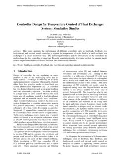
Transcription of CONTROL SYSTEMS AND SIMULATION LAB
1 1 | P a g e CONTROL SYSTEMS AND SIMULATION LAB LAB MANUAL Subject Code : A60290 Regulations : R15 JNTUH Class : III Year II Semester (EEE) DEPARTMENT OF ELECTRICAL AND ELECTRONICS ENGINEERING INSTITUTE OF AERONAUTICAL ENGINEERING (Autonomous) Dundigal, Hyderabad 500 043 2 | P a g e INSTITUTE OF AERONAUTICAL ENGINEERING (Autonomous) Dundigal, Hyderabad - 500 043 Department of Electrical and Electronics Engineering Program Outcomes PO1 Engineering Knowledge: Apply the knowledge of mathematics, science, engineering fundamentals, and an engineering specialization to the solution of complex engineering problems. PO2 Problem Analysis: Identify, formulate, review research literature, and analyze complex engineering problems reaching substantiated conclusions using first principles of mathematics, natural sciences, and engineering sciences. PO3 design / Development of Solutions: design solutions for complex engineering problems and design system components or processes that meet the specified needs with appropriate consideration for the public health and safety, and the cultural, societal, and environmental considerations.
2 PO4 Conduct Investigations of Complex Problems: Use research-based knowledge and research methods including design of experiments, analysis and interpretation of data, and synthesis of the information to provide valid conclusions. PO5 Modern Tool Usage: Create, select, and apply appropriate techniques, APPRATUS, and modern engineering and IT tools including prediction and modeling to complex engineering activities with an understanding of the limitations. PO6 The Engineer and Society: Apply reasoning informed by the contextual knowledge to assess societal, health, safety, legal and cultural issues and the consequent responsibilities relevant to the professional engineering practice. PO7 Environment and Sustainability: Understand the impact of the professional engineering solutions in societal and environmental contexts, and demonstrate the knowledge of, and need for sustainable development. PO8 Ethics: Apply ethical principles and commit to professional ethics and responsibilities and norms of the engineering practice.
3 PO9 Individual and Team Work: Function effectively as an individual, and as a member or leader in diverse teams, and in multidisciplinary settings. PO10 Communication: Communicate effectively on complex engineering activities with the engineering community and with society at large, such as, being able to comprehend and write effective reports and design documentation, make effective presentations, and give and receive clear instructions. PO11 Project Management and Finance: Demonstrate knowledge and understanding of the engineering and management principles and apply these to one s own work, as a member and leader in a team, to manage projects and in multidisciplinary environments. PO12 Life - Long Learning: Recognize the need for, and have the preparation and ability to engage in independent and life - long learning in the broadest context of technological change. Program Specific Outcomes PSO1 Professional Skills: Able to utilize the knowledge of high voltage engineering in collaboration with power SYSTEMS in innovative, dynamic and challenging environment, for the research based team work.
4 PSO2 Problem - Solving Skills: Can explore the scientific theories, ideas, methodologies and the new cutting edge technologies in renewable energy engineering, and use this erudition in their professional development and gain sufficient competence to solve the current and future energy problems universally. PSO3 Successful Career and Entrepreneurship: The understanding of technologies like PLC, PMC, process controllers, transducers and HMI one can analyze, design electrical and electronics principles to install, test , maintain power system and applications. 3 | P a g e INDEX S. No. List of Experiments Page No. 1 Time response of Second Order SYSTEMS 6 - 8 2 Characteristics of Synchros 9 - 12 3 Programmable Logic Controller-Study and verification of truth tables of logic gates, simple Boolean expressions and application of speed CONTROL of motor 13 - 18 4 Effect of feedback on DC servo motor 19 - 21 5 Transfer function of DC motor 22 - 27 6 Effect of P, PD, PI, PID Controller on second order SYSTEMS .
5 28 - 29 7 Lag and Lead compensation - Magnitude and phase plot 30 - 33 8 Transfer function of DC generator 34 - 37 9 Characteristics of magnetic amplifiers 38 - 41 10 Temperature controller using PID 42 - 44 11 Characteristics of AC Servo motor. 45 - 47 12 PSICE SIMULATION of Op-Amp based Integrator and Differentiator circuits 48 - 51 13 Stability analysis (Bode, Root Locus, Nyquist) of Linear Time Invariant system using MATLAB. 52 - 56 14 State space model for classical transfer function using MATLAB 57 -59 4 | P a g e ATTAINMENT OF PROGRAM OUTCOMES & PROGRAM SPECIFIC OUTCOMES Exp. No. Experiment Program Outcomes Attained Program Specific Outcomes Attained 1 Time response of Second Order SYSTEMS PO2, PO4 PSO1, PSO2 2 Characteristics of Synchros PO1, PO2, PO3 PSO2 3 Programmable Logic Controller - Study and verification of truth tables of logic gates, simple Boolean expressions and application of speed CONTROL of motor PO1, PO2, PO3, PO4, PO5 PSO1, PSO2 4 Effect of feedback on DC servo motor PO3, PO6, PO9 PSO1, PSO2 5 Transfer function of DC motor PO2, PO4 PSO2 6 Effect of P, PD, PI, PID Controller on second order SYSTEMS .
6 PO1, PO3, PO4 PSO1, PSO2 7 Lag and Lead compensation - Magnitude and phase plot PO1, PO2, PO3, PO4 PSO1, PSO2 8 Transfer function of DC generator PO1, PO3 PSO1 9 Temperature controller using PID PO1, PO3, PO4 PSO1, PSO3 10 Characteristics of magnetic amplifiers PO1, PO3, PO4 PSO1 11 Characteristics of AC Servo motor. PO1, PO3 PSO1, PSO2 12 PSICE SIMULATION of Op - Amp based Integrator and Differentiator circuits PO1, PO2, PO3, PO4, PO5 PSO1, PSO2 13 Stability analysis (Bode, Root Locus, Nyquist) of Linear Time Invariant system using MATLAB. PO1, PO3, PO4 PSO1, PSO3 14 State space model for classical transfer function using MATLAB PO1, PO2, PO3, PO4, PO5 PSO1, PSO2 5 | P a g e CONTROL SYSTEMS AND SIMULATION LABORATORY OBJECTIVE The objective of the lab is to design a system and calculate the transfer function, analyzing the stability of the system (both open and closed loop, with positive and negative feedback) with time domain approach and frequency response analysis, using MATLAB and also developing the system which is dynamic in nature with state space analysis approach.
7 OUTCOMES: Upon the completion of CONTROL SYSTEMS practical course, the student will be able to attain the following: 1. Recognize the symbols for the different parts of a block diagram: functional blocks, summing blocks and branch points. Simplify a block diagram using block diagram algebra to obtain a transfer function between any two points in the diagram. 2. Model a mechanical (masses, dampers and springs) and electrical system (inductors, resistors, capacitors) in the form of a transfer function. 3. Determine the impulse, step, and ramp response of a system , given a transfer function model. 4. Perform Routh s stability criterion and root locus of a system to determine stability. For SYSTEMS with unknown values, determine the range of values for which the system will be stable and explain how adding a pole or a zero affects the stability. 5. Analyze feedback CONTROL SYSTEMS in the time and frequency domain to use state space concepts to describe SYSTEMS .
8 6. Recognize the type of a system (based on the number of free integrators) and discuss the expected error characteristics as related to step, ramp, and acceleration inputs. 7. Interpret design criteria as related to the closed loop pole location on the complex plane. 8. Draw the frequency response plots like Bode, Nyquist and Polar plots (magnitude and phase) for a given transfer function. 9. design feedback compensators to achieve a set of desired closed loop system characteristics and design a compensator in the frequency domain to meet specific design requirements using a lead compensator, lag compensator, or lead-lag compensator. 10. Develop a PLC program for an automatic CONTROL system of a medium degree of complexity and select the right hardware for a given application. 11. Consider such aspects of the automation system as network communication, human machine interface, safety and protection against interference.
9 6 | P a g e EXPERIMENT - 1 TIME RESPONSE OF SECOND ORDER system AIM: To study the time response of a second order series RLC system . APPRATUS: S. No. Equipments 1 Second order system study unit. 2 Cathode Ray Oscilloscope 3 Multimeter 4 Connecting Leads BLOCK DIAGRAM: Fig Time Response of Second order system CIRCUIT DIAGRAM: Fig Series RLC second order Equilent 7 | P a g e PROCEDURE: 1. Connections are given as per the block diagram. 2. Adjust the input square wave such that the magnitude of the wave is 1V (p-p). (Check the square wave in CRO by placing CRO in Channel 1 mode). 3. Observe the time response on the CRO (Channel 2) by varying the resistance by changing the knob provided on the front panel. 4. Take the corresponding values of Peak Time (TP), Peak Over Shoot ( P) ( Max Peak Value -1) using trace papers. 5. Calculate Damping Ratio ( ), Undamped Natural frequency ( n) from the following formulae = ln ( P) / ( 2 + ln ( P)2 n = / TP (1- 2) 6.)
10 Calculate the parameters L & C of RLC system using the following formulae = (R/2) (C/L) n = 1 / (LC) 7. Now calculate Settling Time (TS), and Damped frequency ( d) using the following formulae TS = 4 / ( n) ------ (2% Settling Time) d = n (1- 2) TABULAR COLUMN: S. No. R L C Maximum Peak ( P) Peak Time (TP) Damping Ratio ( ) Undamped natural frequency ( n) Damped frequency ( d) Settling Time (TS) 1 2 3 4 5 8 | P a g e S. No. R L C Maximum Peak ( P) Peak Time (TP) Damping Ratio ( ) Undamped natural frequency ( n) Damped frequency ( d) Settling Time (TS) 1 2 3 4 5 MODEL GRAPH: Fig - Time Specifications of Second order system RESULT: PRE LAB VIVA QUESTIONS: 1. What are the Open loop and closed loop CONTROL SYSTEMS ? 2. Give the advantages of closed loop CONTROL SYSTEMS . 3. What do you mean by feedback and what are the types of feedback?