Transcription of Control Valves - Modeling and Simulation
1 Control Valves - Modeling and Simulation CRISTIAN PATRASCIOIU1, CASEN PANAITESCU2, NICOLAE PARASCHIV1 1 Computers & Control Department 2 Chemical Engineering Department Petroleum-Gas University of Ploiesti Bd. Bucuresti 39, Ploiesti, 100680 ROMANIA Abstract: - The paper presents the researches of the authors in the Modeling and the Simulation of the Control Valves . The Control systems with the Control Valves are complex structures and non-linear characteristics because the construction and the hydraulic phenomena associated of Control Valves .
2 The authors have elaborated a mathematical model for the Control valve. The model may be utilized to verify the work characteristic of the Control valve for all operating points. The paper has four parts. First part describes the structure of the Control valve. The second part contains the Control valve model elaborated by the authors. The elements of the model are: the centrifugal pump model, the pipe model, the intrinsic and the work model of the Control element. The third part is destined to elaboration of the Simulation program.
3 In the last part, the authors have presented and have analyzed the numerical results of the Simulation . Key-Words: - model, Control valve, hydraulic system, pump, pipe, numerical Simulation 1 Introduction The Control valve represents an important element of the Control systems. The Control valve is a non-linear element, characterized by the complexity of the mechanical construction and the hydraulic phenomena. One important problem of the Control engineers is the work characteristic of the Control valve.
4 This problem forces the Control engineers to model and simulate the Control Valves . The fundament of the Control valve s mathematical Modeling is represented by [1, 2]. The model of the Control valve is used into mathematically model of the Control system. If the Control system is equipped by centrifugal pump, the numerical Modeling of the Control Valves is an actual problem [3, 4]. Usually, the authors present the solutions associated to the operational characteristic of the Control valve determined by using the simplifying hypothesis, which consider that the pipe drop pressure is not modified.
5 The authors of this paper have focused the researches in the domain of the numerical Modeling and Simulation of the Control Valves into Control system equipped by centrifugal pumps. The first part of the researches has been presented in the papers [5, 6]. In the present article, the authors have continued the development and numerically solved of the Control valve model. 2 Control valve element of the Control system The Control valve is an element of the Control system and it is the most widespread Control element in the field of chemical and petrochemical industry.
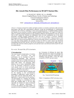
6 The industrial Control valve contains an electronic-pneumatic converter, a pneumatic actuator with membrane and a Control element with a seat, to see the structure presented in figure 1. Fig. 1. The structure of the Control valve The significance of the variables and the subsystems: I/P electro-pneumatic converter; SM actuator; OR Control element; u electrical signal command; pc pneumatic signal command; h the stroke of the actuator; pSM disturbances associated Proceedings of the 5th WSEAS Int.
7 Conf. on DYNAMICAL SYSTEMS and CONTROLISSN: 1790-276963 ISBN: 978-960-474-094-9to the actuator; pOR disturbances associated to the Control element. For the Control system, the Control valve is considered a mono-variable system, the input is the u command of the controller and the output is the manipulated variable m, associated to the process. Many factories made the Control Valves characterized by many constructive tips, by standardized flow module and geometric dimension.
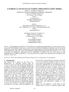
8 An example of the industrial Control valve is presented in figure 2 [7]. The Control valve made of the Pre-Vent [7]. 3 The model of the Control valve in hydraulic systems The authors have elaborated a mathematical model of Control valve. It is based on the following elements: the model of the centrifugal pump; the model of the pipe; the work characteristic model of the Control element; the intrinsic characteristic of the Control element and the energetic balance of the hydraulic system [1, 3, 4, 5 6].
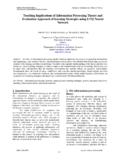
9 The model is defined by the diagram presented in figure 3. The input of the Control valve s mathematical model is the h stroke of the actuator and the output is the Q flow which goes through the valve. The intern variables of the model are: the flow module of the Control valve Kv, the pump output pressure P0,, the drop pressure of the Control valve , the drop pressure of the pipe and the pressure of the exit of the pipe Pout. vP pP Fig. 3. The model of the Control valve in hydraulic systems The model of the centrifugal pump For the chemical and oil refining industry, the most usually hydraulic power source is the centrifugal pump.
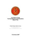
10 In figure 4 is presented a usual centrifugal pump and the various pressure-flow rate characteristics. Fig. 4. The centrifugal pumps and the pressure-flow rate characteristics The mathematical model of the centrifugal pump may be approximated using the following equation: 3322100 QaQaQaaP+++= , (1) where P0 represents the pump output pressure and Q the flow rate. Using the polynomial regression method, the authors have determinate the numerical coefficients of the relation (1), associated to static characteristic pumps presented in figure 4, table 1.