Transcription of Die Attach Film Performance in 3D QFN Stacked Die
1 Die Attach film Performance in 3D QFN Stacked Die. A. JALAR, M. F. ROSLE, M. A. A. HAMID. School of Applied Physics, Faculty of Science and Technology Universiti Kebangsaan Malaysia 43600 UKM Bangi, Selangor MALAYSIA Email : Abstract:- Consumer demand for smaller and lighter products in wiresless application with maximum functionality had drive the semiconductor industries toward the developement of 39dimensional Stacked die. One of the key technology is relies on die stacking process. A suitable bonding condition and material set are essential to achieve required reliability Performance . This study is to relate the effects of variables bonding parameter on the mechanical adhesion and delamination of the die Attach film in QFN Stacked die. Samples are deliberately built with nine combination sets of die Attach parameters including bonding temperature, force and time to achieve a minimum reliability Performance under IPC/JEDEC Moisture Sensitivity Level 3 at reflow 260 C.
2 Characterisation of die Attach film was carried out using differential scanning calorimetry whereas it Performance was carried out using shear testing machine and scanning acoustic test (SAT) is used to detect the interfacial delamination between DAF and die. The best die Attach process is characterized by stable values of die Attach film thermal resistance properties and optimum touch area between die/die Attach film and die Attach film /die. Key-words:- Die Attach film , QFN, delamination 1 Introduction The trend towards miniaturization of wireless devices, more functionality and high Performance can be described by QFN 39dimensional packaging. This innovation introduced the third or Z height dimension by stacking another die on the base die using die Attach film (DAF). 3D packaging offers attractive way to reduce transmission delays, since 3D packaging configuration provides much shorter access to several surrounding chips [1].
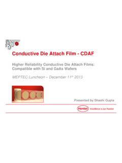
3 Schematic cross section of the stack QFN package can be seen in Fig. 1. There are two common adhesive material used for die stacking in the microelectronic packaging of high9density surface mount epoxy paste and die Attach film (DAF). The application of epoxy paste for die stacking is well documented as a standard die bonding material. Challenge in controlling the resin bleed and creeping effect to the die edge especially for Stacked die need an advanced solution for optimum Performance . To overcome this problem, the usage of DAF was introduced in the development of 39D Stacked die. Evaluation of different die Attach film (DAF) and paste for Stacked die package has been performed using both experimental and modeling works [2].Table 1 shows the usage comparison of DAF and epoxy paste. Fig. 1 Stacked die QFN package Table 1. Comparison of DAF and epoxy paste. Item Die Attach film Epoxy Paste Storage Condition Room Temperature Freezer Adhesive formation Uniform amount Dot patterning WSEAS TRANSACTIONS onAPPLIED and THEORETICAL MECHANICSA.
4 Jalar, M. F. Rosle and M. A. A. HamidISSN: 1991-8747104 Issue 3, Volume 3, March 2008 Die mounting Method Direct bonding Dispenser system Die mounting Temperature Required Not necessary Bleeding No Possible Bond line Thickness Uniform Varied Compared to epoxy, the DAF requires some bonding delay and temperature to allow the DAF to melt, solidifies and stick to the leadframe. One of the important discussion focuses in the stack QFN process flow is on die to die bond process. Basically, when choosing the DAF there are two considerations need to be taken into calculation. First consideration is on the DAF material repeated heat cure during the die Attach , wirebond and moulding process. If the DAF is cured before moulding process, chance of delamination between die and DAF interface is high [3]. Secondly, the optimization on the methods of the die Attach process, to ensure the robustness and reliability of the package.
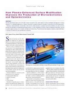
5 Theoretically, it is well agreed that process condition and material properties related to polymeric materials give high impact to the surface mount adhesion. Results from the engineering study shows water absorption and work of adhesion between silicon die and substrate interface decreased with increasing filler [4] resulted to excellent resistance to package cracking during reflow soldering by prevented popcorn phenomenon [5]. When the die stress in the assembly processes is compared, it is found that highest stress occurred after molding and DAF showed 42% lower stress than epoxy [6]. On the other hand, it is clear that after die Attach process, the curing reaction of DAF should be stable in the followed process before mold, to increase the effective touched areas and prevent weak interface or delamination in the stack die product [7]. 2 Experimental Work Sample Preparation of QFN Stack Die Fig.
6 2 shows the schematic of the assembly process flow for the QFN Stacked die sample preparation, starting from wafer thinning until decapsulation process. To maintain a low9profile Stacked die package, the wafers were backgrind to be very thin as mm in thickness. Wafers of 8 inches diameter, 725 Lm thickness and <100> orientation were used in this study. For the mechanical backgrinding step, the abrasive diamond wheels with grit size mesh #1500 were used. After the backgrinding process, some wafers undergo the surface recovery by chemical wet etching at a standard removal rate. The end thickness for wafers undergoing stress relief process was 150 Lm. Wafer Thinning DAF Laminating Wafer Dicing Bottom Die Attach Die Pick9up Top Die Attach Molding WSEAS TRANSACTIONS onAPPLIED and THEORETICAL MECHANICSA. Jalar, M. F. Rosle and M. A. A. HamidISSN: 1991-8747105 Issue 3, Volume 3, March 2008 Fig.
7 2 The schematic illustrate the process flow of QFN Stack Die. DAF tape was laminated at the backside of thin wafer by applying the same concept as laminating the conventional tape. During lamination inter liner tape will be release and DAF tape will be place on the wafer backside with a roller will be roll on the surface. This is to make sure an even surface with free bubble trap between the tapes and wafer backside. The only response that can be observed was particles exist in between the wafer and the DAF tape. The particles will only affect the dicing process if the particles are in large size but particles size that being observed in the experiment were very small and doesn t give a significant impact to the dicing process such as flying dies. Double pass dicing method was used to reduce lateral crack and chipping problem in dicing 150Lm thickness wafer laminated with DAF as proposed by Jiun et al.
8 [8]. In the dicing process the critical parameter such as spindle rotation, saw speed, and blade grit size has been determined by experimental works and the outcome meet a good agreement with the study done by Abdullah et al [9]. Evaluation on the die pick up conditions has been earlier made to observe the effect of pick up force, needle size and height on the die crack and needle mark. These results are important to ensure that any failure at pick up process will not affect the bonding results while running the die bond evaluation. Final results concluded that 5 mil needle type with force 50 gf and mm needle height are able to give good pick up condition on x mm2 die size with no needle mark and no die crack observed by visual inspection. illustrate the comparison of the poor and good DAF surface after die pick9up process. (a) (b) Fig. 3 Die pick up results (a) needle mark observed (b) no needle mark observed with optimized pick9up condition.
9 During Stacked die Attach process, samples were prepared using thin film of Al die with the package size of 7 x 7 x mm3, QFN 48 leads package. The bottom die size was 5 x 5 mm2 and the top die size was x mm2, with thickness for both dies were mm. The samples were deliberately built with nine combination sets of die bonding parameters for top die laminated with DAF while bottom die Attach process were performed using commercial epoxy with only maintain at one optimized die Attach parameter as shown in Table 2. Table 2. Parameter matrix for top die Attach . WSEAS TRANSACTIONS onAPPLIED and THEORETICAL MECHANICSA. Jalar, M. F. Rosle and M. A. A. HamidISSN: 1991-8747106 Issue 3, Volume 3, March 2008 The die Attach process started with attachment of the bottom die by following the normal epoxy dispenser process and then cured in the oven at 160 C for one hour. DAF Y was used to stack up the DAF laminated die on the top of the bottom die by using the same ESEC2008HS but equipped with the Heated Process Positions (HPPS).
10 At this stage the dispenser system which used in the mounting method for epoxy was eliminated and the DAF die bonding process was assisted by the heater or HPPS system and need some bonding delay to allow the DAF to melt, solidifies and stick to the leadframe. Stacked die samples were cured in the oven at 150 C for one hour. All the samples were then past through the molding process using commercial mold compound with optimized parameter. Molding temperature was set at 175 C. Finite Element Analysis (FEA) FEA was used to simulate three different temperatures of manufacturing processes for top die laminated with DAF Y to determine the die stress at each stage. From the data sheet given by the supplier, the recommended temperature range for die Attach process using DAF Y are within 100~150 C. Thus to support the experimental results, simulation was run between three different die Attach temperatures at 100 C, 125 C and 150 C.