Transcription of Controller Area Network (CAN) Tutorial - NI
1 Controller Area Network (CAN) Tutorial A Controller Area Network (CAN) bus is a high-integrity serial bus system for networking intelligent devices. CAN busses and devices are common components in automotive and industrial systems. Using a CAN interface device, you can write LabVIEW applications to communicate with a CAN. Network . Topics A. What You Need to Get Started B. History of CAN. C. CAN Basics D. Channel Configuration E. CAN APIs F. CAN Programming in LabVIEW (Channel API). National Instruments Corporation 1-1 Controller Area Network (CAN) Tutorial A. What You Need to Get Started Tutorial Materials Before you use this Tutorial , ensure you have all the following items: Windows 2000 or later installed on your computer.
2 The Tutorial is optimized for Windows XP. Multifunction DAQ device configured as device 1 using Measurement & Automation Explorer (MAX). LabVIEW Full or Professional Development System 2009 or later A CAN Interface NI-CAN or later Exercises folder for saving VIs created during the Tutorial and for completing certain Tutorial exercises Solutions folder containing the solutions to all the Tutorial exercises B. History of CAN. In the past few decades, the need for improvements in automotive technology caused increased usage of electronic control systems for functions such as engine timing, anti-lock brake systems, and distributorless ignition. Originally, point-to-point wiring systems connected electronic devices in vehicles.
3 More and more electronics in vehicles resulted in bulky wire harnesses that were heavy and expensive. To eliminate point-to-point wiring, automotive manufacturers replaced dedicated wiring with in-vehicle networks, which reduced wiring cost, complexity, and weight. In 1985, Bosch developed the Controller Area Network (CAN), which has emerged as the standard in-vehicle Network . CAN provides a cheap, durable Network that allows the devices to speak through the Electronic Control Unit (ECU). CAN allows the ECU to have one CAN interface rather than analog inputs to every device in the system. This decreases overall cost and weight in automobiles.
4 Each of the devices on the Network has a CAN Controller chip and is therefore intelligent. All transmitted messages are seen by all devices on the Network . Each device can decide if the message is relevant or if it can be filtered. Controller Area Network (CAN) Tutorial 1-2 As CAN implementations increased in the automotive industry, CAN (high speed) was standardized internationally as ISO 11898. Later, low-speed CAN was introduced for car body electronics. Finally, single-wire CAN was introduced for some body and comfort devices. Major semiconductor manufacturers such as Intel, Motorola, and Philips developed CAN chips. By the mid-1990s, CAN was the basis of many industrial device networking protocols, including DeviceNet and CANOpen.
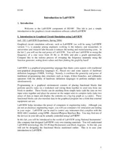
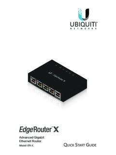
5 Automotive Applications Examples of CAN devices include engine Controller (ECU), transmission, ABS, lights, power windows, power steering, instrument panel, and so on. Automotive CAN Devices Instrument Panel Power Steering Power Windows Transmission Lights ABS. Figure 1-1. Automotive CAN Devices Other CAN Markets Comparing the requirements for automotive and industrial device networks showed the following similarities: the transition away from dedicated signal lines low cost resistance to harsh environments real-time capabilities These similarities led to the use of CAN in industrial applications such as textile machinery, packaging machines, and production line equipment such as photoelectric sensors and motion.
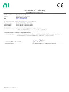
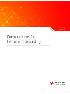
6 With its growing popularity in automotive and industrial applications, CAN. has been increasingly used in a wide variety of applications. Usage in systems such as agricultural equipment , nautical machinery, medical apparatus, semiconductor manufacturing equipment , avionics, and machine tools validate the versatility of CAN. National Instruments Corporation 1-3 Controller Area Network (CAN) Tutorial Military Public Systems Transportation CAN. Farm Avionics Machinery Other Applications Including Medical Devices Printing Machines Figure 1-2. Other CAN Markets C. CAN Basics Benefits of CAN. Lower cost from reduced wiring compared to two wire, point-to-point wiring Highly robust protocol Built-in determinism Fault tolerance Reliable More than a decade of use in the automotive industry CAN Specifications CAN data (up to 8 bytes in a frame).
7 Maximum 1 Mbaud/s 40 Meters at 1 Mbaud/s 6 km at 10 kbaud/s Theoretical maximum of 2,032 nodes per bus Practical limit is approximately 100 nodes due to transceiver Most buses use 3 10 nodes Data fields Arbitration ID (11 bit or 29 bit). Indicates message priority Types of CAN. High Speed CAN. Up to 1 M bits/s transmission rate Controller Area Network (CAN) Tutorial 1-4 Low Speed/Fault-Tolerant CAN. Up to 125 kbaud/s transmission rate Fault tolerant Single Wire Up to kbaud/s High-voltage pulse to wakeup sleeping devices NI CAN Interface Devices National Instruments provides four types of CAN interface devices that use the NI-CAN API described in this appendix.
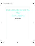
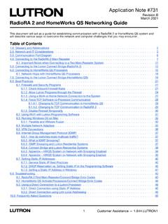
8 Each category of devices supports multiple form factors and is available in one or two port varieties. High-speed CAN. 1 and 2 ports Maximum baud rate of 1Mb/s Low-speed CAN. 1 and 2 ports Maximum baud rate of 125 kbaud/s Software Selectable CAN. 1 and 2 ports (each port can be used as high-speed, low-speed, or single-wire CAN). Single Wire CAN. 1 and 2 ports Maximum baud rate of kbaud/s CAN Frame CAN devices send data across the CAN Network on packets called frames. A typical CAN frame contains an arbitration ID, a data field, a remote frame, an error frame, and an overload frame. National Instruments Corporation 1-5 Controller Area Network (CAN) Tutorial Standard Frame Format S 11-Bit R I A.
9 O T D DLC 0 8 Data Bytes 16-Bit CRC C End of Frame F Arbitration ID R E K. Extended Frame Format S High 11-Bits I Low 10-Bits R A. O D T DLC 0 8 Data Bytes 16-Bit CRC C End of Frame F of Arbitration ID E of Arbitration ID R K. Figure 1-3. Standard and Extended CAN Frames Arbitration ID. The arbitration ID determines the priority of the messages on the bus. If multiple nodes try to transmit a message onto the CAN bus at the same time, the node with the highest priority (lowest arbitration ID) automatically gets bus access. Nodes with a lower priority must wait until the bus becomes available before trying to transmit again. The waiting devices wait until the end of the frame section is detected.
10 Device A transmits 1 1 0 0 1 0 0 0 1 1 1. ID = 110 0100 0111 (647 hex). Device B transmits 1 1 0 1. ID = 110 1100 0111 (6C7 hex). Device B loses and goes idle until end of frame Device A wins, and proceeds Figure 1-4. CAN Arbitration Data Field The data field contains the actual data being transmitted. The CAN protocol supports two data field formats as defined in the Bosch Version specifications, the essential difference being in the length of the arbitration ID. In the standard frame format (also known as ), the length of the ID. is 11 bits. In the extended frame format (also known as ), the length of the ID is 29 bits. In NI-CAN terminology, a data field for which the individual fields are described is called a message.