Transcription of Cooldek Outback Flat Attached Installation Guide - Stratco
1 INSTALLATIONGUIDEO utback flat AttachedWITH Cooldek ROOFINGIt is important to check your Local Government Authority requirements before the Installation of your new Stratco Outback with Cooldek flat Verandah. It is the builder s responsibility to ensure any existing structure that an Outback is being Attached to is adequately reinforced to accommodate the additional loads imposed by the verandah, patio or carport. Read these instructions thoroughly before starting your project and refer to them constantly during each stage of construction.
2 Contact Stratco for advice if you do not have the necessary tools or information. Before starting, lay out the main components in order of assembly on the ground and check them against the delivery note. The Components section identifies each part of your Outback flat Verandah with Cooldek and shows the relative location of the components. Mark out the overall area of your verandah, patio or carport and ensure that it is free from obstructions. Beam to wall connections can cause difficulty if they coincide with windows and door openings, so avoid these in your design.
3 Ensure there is reasonable access for materials and working space and consider the disposal of run-off water. Check the column and beam positions on the ground; roughly check they are square by measuring the diagonals, then mark out the column locations. If columns are to be in ground , dig the holes to Stratco YOU STARTThe Outback kit does not include fixings to attach the unit to an existing structure or concrete/masonry anchors for the column Installation . If required, they must be purchased as additional MATERIALS Drill & Hex head Adaptor (5/16 & 3/8) Rivet Gun Tape Measure Tin Snips Spirit Level Hack-Saw Post Hole Digger Silicone Gun Spanner or Ratchet Adjustable Construction Props Turn Up/Down Tool Concrete LadderTOOLS REQUIREDC utback FlashingSide Cap FlashingBack ChannelWith BIP FoamSide Cap FlashingDOWNPIPEF unnels water from the gutter to the ground via an outlet.
4 Accessories of mitres, shoes and brackets are available as optional BRACKETC onnects post to CAPF ills the gap between the post and SCREWS WITH CYCLONE CAP AND NEOPRENE WASHERUsed to fix insulted deck into beams. FOOTING PLATES68 Outback column footing BRACKETR eplaces the wall brackets when the beam is suspended from the fasciaCOMPONENTSFLASHING LAYOUTSCREWS AND RIVETSF astener types vary depending upon the connection, ensure the correct fixings are guttercutback flashingcutback flashing Attached to panel under sheetgutter strapgutter riveted to cutback flashing and top sheetgutter strap riveted to sealed riv sealed riv etsreceiving sealed riv etsreceiving sealed riv sealed riv etsreceiving channelGUTTER STRAP AND STOP ENDOUTBACK BEAMSThe beams are the frame to support the the beam FLASHINGSIDE CAP FLASHINGBACK CHANNELWALL BRACKETF astens the Outback beams directly to a INLINE CONNECTORSJ
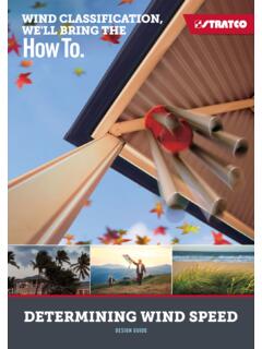
5 Oins beams flush to form a continuous beam. Different connectors are available for various angles and FILLERSF ills gap between intersecting beams. A notched version is available where a column also END CAPE ncloses the end of the TO BEAM BRACKETC onnects horizontal Insulated Roofing sheetsCOOLDEK CLASSICCOOLDEK CGIGUTTERThe gutter adjoins the roof to catch water run off. Stop ends, outlets, straps and brackets are available. Two 12x20 self-drillingscrews on each side15mmWall BracketTwo M8 masonry anchors or two 8mm diameter screwbolts with a minimum embedment of 65mmWALL BRACKETFor units Attached to a wall, position the wall brackets where the beams meet the wall.
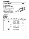
6 The folded section on the tabs of the bracket is located at the top. The highest point of the wall bracket will be 15mm below the top of the beam. Mark the holes and drill using an 8mm masonry bit. Fasten the bracket to the wall with two M8 masonry anchors to a minimum 65mm embedment. The beam is slid into position and fastened with four 12x20 self drilling screws (Figure ). Back channel not CHANNEL INSTALLATIONBRACKETSF igure CHANNELThe shorter edge of the back channel is the underside.
7 The back channel should run from the outside edges of the side beams. If multiple lengths are required, butt the channels together and waterproof with what type of fascia you are attaching your unit to and what type of fixings and brackets you require. Pre-drill the back channel on the ground. Locate the first hole 100mm from the edge of the back face of each length of channel. Drill the other holes at 500mm centres for timber and brickwork or 250mm centres for steel fascia.
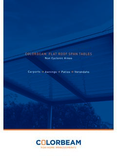
8 Run two beads of silicone along the back of the back channel, with one near the top edge to ensure a water tight ATTACHMENTWhen fixing the back channel to fascia, the roofing above each rafter must be removed to give adequate space to install the fascia strengthening brackets. M10 Bolts connect the brackets to the rafter and fascia (the number of brackets required is determined by the builder, but the spacing should not exceed 1200mm). Silicone as shown in the diagrams. When fixing to timber fascia (Figure ) attach the back channel using 12x25mm hex head timber fixing screws through the pre-drilled holes.
9 When fixing to steel fascia (Figure ) attach the back channel using 12x20mm hex head self drilling screws through the pre-drilled holes. The back channel is bolted through the fascia to the fascia brackets with one M10 bolt per bracket. Insert BIP foam into the top half of the back channel, this acts as a weather seal when the roof sheets are pressed into TO A BRICK WALLWhen fixing the back channel to a brick wall, pre-drill the anchor holes using a masonry drill bit. Attach the back channel using M6x65mm masonry anchors through the pre-drilled holes (Figure ).
10 Insert the BIP foam into the back channel, this acts as a weather seal when the roof sheets are pressed into HOUSE FRAME ATTACHMENTWhen fixing the back channel to the steel fascia on a steel framed house, the roofing above each rafter must be removed to allow enough room to install the rafter strengthening brackets. Attach angle brackets to RHS reinforcement using 12x20 self drilling screws. Place the brackets above the first web or truss connection at least 900mm from the wall, and directly over the wall.